Optimal configuration of 10 kV power distribution network parallel reactor and compensation method of 10 kV power distribution network parallel reactor

A technology for optimizing configuration and compensation methods, applied in reactive power compensation, reactive power adjustment/elimination/compensation, etc., can solve problems such as reluctance of power plant operators, increased costs, and stability impact of active output units

Inactive Publication Date: 2013-05-08
SOUTH CHINA UNIV OF TECH
View PDF3 Cites 14 Cited by
  • Summary
  • Abstract
  • Description
  • Claims
  • Application Information

AI Technical Summary

Problems solved by technology

[0006] (1) Lack of phase-advance operation tests and specific operating procedures
In particular, the lack of experience in phase-advancement operation of small hydropower units makes power plant operators unwilling to implement phase-advancement when the voltage is high
[0007] (2) The quality of personnel on duty in small hydropower plants is relatively low, and phase-advancing operation increases the difficulty of operation, and power plant operators do not want to increase costs
[0008] (3) Traditional power factor assessment meas...

Method used


Image

  • Optimal configuration of 10 kV power distribution network parallel reactor and compensation method of 10 kV power distribution network parallel reactor
  • Optimal configuration of 10 kV power distribution network parallel reactor and compensation method of 10 kV power distribution network parallel reactor
  • Optimal configuration of 10 kV power distribution network parallel reactor and compensation method of 10 kV power distribution network parallel reactor

Examples


Embodiment Construction

[0077] An optimized configuration of a distribution network 10kV shunt reactor proposed by the present invention and its compensation method are described in detail in conjunction with the embodiments as follows:

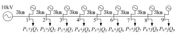
[0078] figure 1 It shows the ideal distribution line model for the connection of small hydropower string lanterns. Each node of the main line has a small hydropower plant with a capacity of 300kW. The wire type is LGJ-120, and the corresponding reactance value per km is X 0 is 0.42Ω, and the length of each line is 3km.

[0079] This method comprises the following steps:

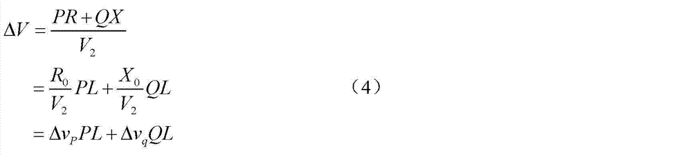
[0080] Step S1, by decoupling the voltage drop formula to obtain the voltage drop reactive power decoupling formula, the specific steps are as follows:

[0081] Step S11, the phase voltage at the head end of the transmission line is:

[0082] V · 1 ...


PUM


Abstract

The invention provides an optimal configuration of a 10 kV power distribution network parallel reactor and a compensation method of the 10 kV power distribution network parallel reactor. The optimal configuration of the 10 kV power distribution network parallel reactor and the compensation method of the 10 kV power distribution network parallel reactor are used for solving the problem that inductive reactive power optimal allocation of resources of insertion of small hydro to power distribution network and controlling switching of the reactive power compensation. The compensation method of the 10 kV power distribution network parallel reactor comprises the following steps: obtaining a voltage drop reactive decoupling formula by means of a decoupling deduction of the voltage drop formula; ensuring reactive decoupling coefficient according to the line reactance per kilometer and the line voltage reference; ensuring an optimal configured compensation point of the 10 kV parallel reactor according to the voltage drop reactive decoupling formula; ensuring and avoiding the capacity of the 10 kV parallel reactor configuration of the upper limit of the node voltage of a trunk line, and ensuring the capacity of a single unit and the number of configured groups of the 10 kV parallel reactor by a reference of a rule that a voltage regulating effect of reactive compensation equipment of a single group of a transformer substation does not exceed 2.5% of the rated voltage; and monitoring the node voltage of the trunk line including the small hydro in real time, and controlling the switching of the 10 kV parallel reactor according to the voltage drop reactive decoupling formula.

Description

technical field [0001] The invention relates to optimal configuration and switching control of inductive reactive power compensation equipment in a distribution network, in particular to an optimal configuration and compensation method for a 10kV shunt reactor adapted to connect small hydropower to a distribution network. Background technique [0002] In some areas with relatively rich water resources in my country, the installed capacity and construction scale of small hydropower are rapidly expanding. With the gradual increase of the proportion of small hydropower in the power grid, small hydropower has an important impact on the reactive power and voltage quality of the regional power grid. Due to the fact that most of the current small hydropower plants are run-of-the-river and lack adjustment capabilities, centralized power generation often causes imbalances in power generation and power consumption in regional small hydropower grids during the wet season, causing line v...

Claims


Application Information

Patent Timeline
IPC IPC(8): H02J3/18
CPCY02E40/30
Inventor 张勇军张锡填刘伦
Owner SOUTH CHINA UNIV OF TECH
Why Eureka
Try Eureka