
A mobile power circuit

A mobile power supply and charging circuit technology, applied in battery circuit devices, circuit devices, collectors, etc., can solve the problems of single function of mobile power supply, inconvenient management and portability, inconvenient use, etc., and achieve stable work, convenient travel, and simple circuits Effect

Active Publication Date: 2015-11-18
ANHUI TIANTANG WEIGAO PLASTIC TECH
View PDF2 Cites 0 Cited by
  • Summary
  • Abstract
  • Description
  • Claims
  • Application Information

AI Technical Summary

Problems solved by technology

[0002] In real life, with the rapid development of science and technology, people's living standards are also improving day by day. They often need to carry a variety of electronic products to go out to work or travel. There are also a variety of spare batteries. When the power is exhausted, each battery needs to be charged. This is not easy to manage and carry, and it is troublesome to charge. The existing mobile power supply has a single function and is inconvenient to use. A more functional power supply circuit is needed to solve this problem.

Method used


Image

  • A mobile power circuit

Examples


Embodiment Construction

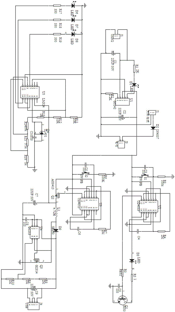
[0015] Such as figure 1 As shown, a mobile power supply circuit includes a lithium battery charging circuit, a solar charging circuit, a lighting circuit, a switch control circuit, a charging circuit and a power prompt circuit;

[0016] The lithium-ion charging circuit is connected to pin 4 of the lithium battery charging management chip U1 through the miniUSBJ1 through the filter capacitor C19, and then leads from the pin 4 to the resistor R1 to the light-emitting diode D1 to pin 1 of the chip U1. Pin 2 is grounded, pin 3 of chip U1 is connected to the positive pole of lithium battery J3 through filter capacitor C2, and pin 5 is grounded through resistor R2;

[0017] The solar charging circuit is that the output of the solar panel is connected to the positive pole of the lithium battery J3 through the rectifier diode D2;

[0018] The lighting circuit is that pin 1 and pin 11 of the chip U2 are connected to connect a resistor R4 to the ground through a capacitor C4, pin 4 of ...


PUM


Abstract

The invention discloses a mobile power source circuit which comprises a lithium battery charging circuit, a solar charging circuit, a lighting circuit, a switch control circuit, a charging circuit and an electric quantity prompting circuit. The mobile power source circuit is applied to a mobile power source which needs multiple functions. The mobile power source circuit is concise, not easy to go wrong, easy to operate and control, low in power loss, capable of achieving multiple functions, stable to work, low in manufacture cost, strong in practicability and capable of bringing a great number of convenience for people to travel.

Description

technical field [0001] The invention relates to the field of mobile power supplies, in particular to a mobile power supply circuit. Background technique [0002] In real life, with the rapid development of science and technology, people's living standards are also improving day by day. They often need to carry a variety of electronic products to go out to work or travel. There are also a variety of spare batteries. When the power is exhausted, each battery needs to be charged. This is not easy to manage and carry, and charging is also cumbersome. The existing mobile power supply has a single function and is inconvenient to use. A more functional power supply circuit is needed to solve this problem. Contents of the invention [0003] The purpose of the present invention is to provide a mobile power supply circuit capable of realizing multiple functions in order to remedy the defects of the prior art. [0004] The present invention is achieved through the following technica...

Claims


Application Information

Patent Timeline
Patent Type & Authority Patents(China)
IPC IPC(8): H02J7/00
Inventor 程为高
Owner ANHUI TIANTANG WEIGAO PLASTIC TECH
Learn More