A device and method for cleaning crankcase gas

A crankcase, cleaning technology, applied in the direction of crankcase ventilation, engine components, machine/engine, etc., can solve the problems of reducing the separation efficiency of centrifugal rotors and reducing centrifugal rotors, etc.

Active Publication Date: 2013-05-08
ALFA LAVAL CORP AB
View PDF6 Cites 7 Cited by
  • Summary
  • Abstract
  • Description
  • Claims
  • Application Information

AI Technical Summary

Problems solved by technology

However, reducing the rotational speed of the centrifugal rotor will also reduce the separation efficiency of the centrifugal rotor

Method used


Image

  • A device and method for cleaning crankcase gas
  • A device and method for cleaning crankcase gas
  • A device and method for cleaning crankcase gas

Examples


Embodiment Construction

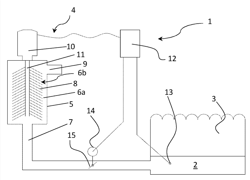
[0020] figure 1 A first embodiment of a device 1 for cleaning crankcase gases generated in a crankcase 2 during operation of an internal combustion engine 3 is disclosed. The combustion engine 3 can be, for example, a diesel engine mounted on a locomotive or a truck. The device 1 comprises a centrifugal separator 4 with a housing 5 delimiting a separation chamber 6a, wherein a centrifugal rotor 6b is arranged for cleaning said crankcase gases and is arranged, by its rotation, to remove the crankcase gases from the crankshaft Tank 2 is pumped to centrifugal separator 4 . Such centrifugal separators arranged to suck or pump crankcase gases from the crankcase are described in more detail, for example, in EP 1532353 B1 and / or WO 2010 / 008342 A1. The housing 5 of the centrifugal separator 4 is connected to the crankcase 2 via a gas inlet 7 in the form of a line arranged between the centrifugal separator 4 and the crankcase 2 . The gas inlet 7 is configured to guide crankcase gase...


PUM


Abstract

The present invention relates to a device (1) and method for cleaning of crankcase gas being produced in a crankcase (2) during operation of an internal combustion engine (3). The device (1) comprises a centrifugal separator (4) having a housing (5) and a separation chamber (6a) in which a centrifugal rotor (6b) is arranged for cleaning of said crankcase gas. The separator (4) is connected to a gas inlet (7) for conducting crankcase gas from the crankcase (2) to the centrifugal separator (4) and a gas outlet (9) for conducting the cleaned gas from the separator (4). A motor (10) is arranged to rotate the centrifugal rotor (6b) with control equipment (12) for changing the rotational speed of the centrifugal rotor (6b). A sensor (13) is provided for detection of a parameter, the magnitude of which is related to a gas pressure in the crankcase (2). The sensor (13) is arranged to communicate with the control equipment (12) of the motor, the control equipment (12) being operatively connected to a valve (15, 15') which is arranged for adjusting the flow of gas through the centrifugal separator (4). The control equipment (12) is arranged to change the position of the valve (15, 15') in response to a detected change of said parameter in a way such that the gas pressure in the crankcase (2) is maintained at a predetermined value, or at a predetermined pressure interval, during operation of the combustion engine.

Description

technical field [0001] The invention relates to a device for cleaning crankcase gases generated during operation of an internal combustion engine, said device comprising a centrifugal separator comprising a housing delimiting a separation chamber in which a centrifugal rotor is arranged for For cleaning said crankcase gases, wherein a centrifugal separator is connected to a gas inlet for directing a flow of crankcase gas from the crankcase to the centrifugal separator and to a gas outlet for directing a flow of gas from the centrifugal separator. A motor is arranged for rotation of the centrifugal rotor, the motor being arranged with control equipment for varying the rotational speed of the motor and thus of the centrifugal rotor. The device also includes a sensor for detecting a parameter whose magnitude is related to the gas pressure in the crankcase, the sensor being arranged in communication with the control equipment of the motor. Background technique [0002] One prob...

Claims


Application Information

Patent Timeline
Patent Type & Authority Applications(China)
IPC IPC(8): F01M13/04
CPCF01M2013/0044F01M2013/0422F01M13/04F01M2013/0005
Inventor J.斯库格
Owner ALFA LAVAL CORP AB
Why Eureka
Try Eureka