Canal type thickener

A thickener and channel-type technology, applied in the field of thickeners, can solve the problems of restricting the application of small and medium-sized mineral processing enterprises, large area and high cost, saving materials, solving the effect of large area and long channels

Inactive Publication Date: 2013-05-15
蔡宏武
View PDF4 Cites 12 Cited by
  • Summary
  • Abstract
  • Description
  • Claims
  • Application Information

AI Technical Summary

Problems solved by technology

[0003] The existing technology can achieve the purpose of solid-liquid enrichment and separation, but the traditional thickener equipment is large in size, large in floor space, and high in cost, which restricts its application in small and medium-sized mineral processing enterprises

Method used


Image

  • Canal type thickener
  • Canal type thickener

Examples


Embodiment 1

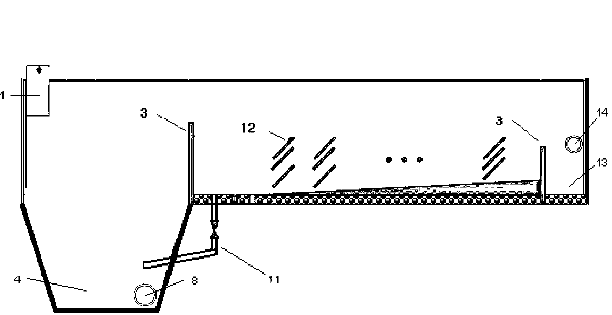
[0037] The canal thickener of this embodiment is a channel type as a whole. It includes a canal head a, a canal body b, and a canal tail c along the flow path of the slurry. There are partitions between the canal head a, canal body b, and canal tail c. 3 separate, and the partition 3 between the canal tail c and the canal body b is lower than the partition 3 between the canal head a and the canal body b to ensure the flow direction of the slurry from the canal head a to the canal tail c; The canal head a includes a feed port 1, a thick pool 4, and a discharge port 8. The slurry enters the thick pool 4 from the feed port 1, and the discharge port 8 is located at the bottom of the thick pool 4; and a surface is distributed in the canal body b. The settling sloping plate 12 facing the direction of the slurry flow and rising along the direction of the slurry flow, the bottom height of the canal body b rises in the direction of the water flow, and the bottom of the front end part is ...

Embodiment 2

[0040] In this example, the tailings discharged from the iron dressing plant, the amount of tailings discharged from the iron dressing plant is G=120m3 / h, and the concentration is 15%. The width of the canal b=1m, the height of the canal water level h=1m, and the number of settlement slopes in each group n=10, then it can be calculated

[0041] V 2 =G / (3600bh)=120 / (3600×1×1)=0.033333m / s

[0042] t=H / V 1 =(h / n) / V 1 =(1 / 10) / (0.33×10 -4 )=3030s

[0043] L=tV 2 =3030×0.033333=101m

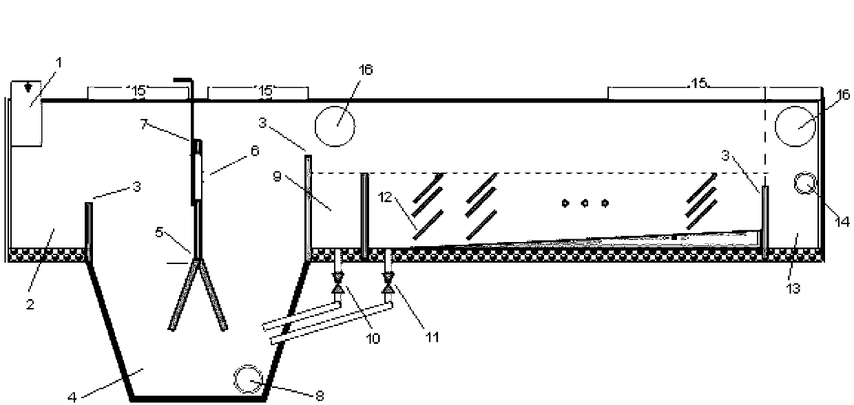
[0044] The ore pulp enters the receiving pool 2 through the feeding port 1, and crosses the partition 3, and the heavy particles in the ore pulp settle in the thick pool 4. The dense pond 4 is divided into two parts on the left and the right by a herringbone 5, and the herringbone increases the tortuosity of the water flow and reduces the settlement height, thereby accelerating the settlement. A water-permeable window 6 is installed on the chevron to adjust the ratio of the amount of slurry flowing through t...


PUM

PropertyMeasurementUnit
widthaaaaaaaaaa
lengthaaaaaaaaaa

Abstract

The invention relates to a canal type thickener, which is a canal overall. Along an ore pulp flow path, the thickener includes a canal head, a canal body and a canal tail in order. Ore pulp enters a thickening pond through a feeding port, heavy particles in the ore pulp undergo preliminary settlement in the thickening pond. The low concentration ore pulp overflowing the canal head enters the canal body to undergo further settlement. When the low concentration ore pulp flows to the canal tail, it is already in a clear water state basically and enters a clear water pond, and is discharged through a drain hole. In the invention, the thickener is changed from the traditional ''round pond'' type to the ''canal type'', thus effectively solving the problem of large floor area of the thickener. The canal structure is in linear arrangement, can be subjected to buried installation, and does not take up the volume of a concentrating mill basically. With a long canal and a large actual settlement area, the structure of the thickener can be simpler, thereby effectively reducing the production cost.

Description

Technical field [0001] The invention relates to a thickener, which belongs to the field of beneficiation. Background technique [0002] The thickener is a solid-liquid separation equipment based on gravity sedimentation that is commonly used in mineral processing enterprises. The prior art generally adopts a cylindrical or round pool-shaped trough structure. After slow rotation, the thickened underflow slurry is removed from the thickener. The underflow port at the bottom is discharged, and the clearer liquid (overflow) is produced at the upper part of the thickener, which is discharged from the annular chute at the top. [0003] The existing technology can achieve the purpose of solid-liquid enrichment and separation, but the traditional thickener is large in volume, large in area, and high in cost, which restricts its application in small and medium-sized beneficiation enterprises. Summary of the invention [0004] In order to solve the above-mentioned problems, the present inven...

Claims


Application Information

Patent Timeline
Patent Type & Authority Applications(China)
IPC IPC(8): B01D21/02
Inventor 蔡宏武
Owner 蔡宏武
Why Eureka
Try Eureka