Damper indicator diagram test fixture
A technology for testing fixtures and shock absorbers, which is applied to instruments, power metering, and measuring devices. It can solve problems such as low work efficiency, complex structure, and high labor intensity for operators, and achieve simple structure, convenient disassembly, and improved testing efficiency. Effect
- Summary
- Abstract
- Description
- Claims
- Application Information
AI Technical Summary
Problems solved by technology
Method used
Image

Examples
Embodiment Construction
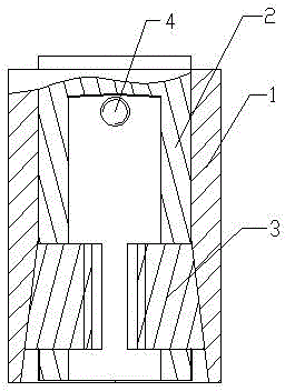
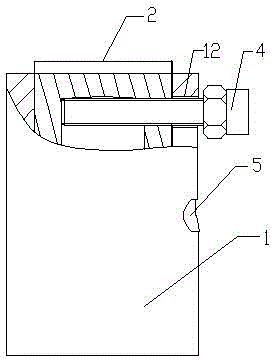
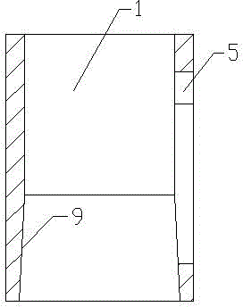
[0018] Such as figure 1 and 2 As shown, the shock absorber dynamometer test fixture includes a sleeve 1, a fixture seat 2, a wedge-shaped clamp block 3 and a limit rod 4. The sleeve 1 and the fixture seat 2 are hollow cylindrical structures, and the sleeve 1 is set on the fixture seat. 2, two opening slots 6 are symmetrically arranged on the fixture seat 2, and a wedge-shaped clamping block 3 is respectively installed in the opening slots 6, and the limit slide groove 5 is arranged on the sleeve 1, and the inner wall of one end of the sleeve 1 is opened outward. The conical surface 9 of the wedge-shaped clamp block 3 is a conical surface 10 matched with the conical surface 9 of the sleeve 1, the inner surface of the wedge-shaped clamp block 3 is provided with a thread 11, one end of the stop rod 4 is connected to the clamp seat 2, and the other end is connected to the clamp seat 2 from the The limit chute 5 extends out of the outer surface of the sleeve 1, the limit rod 4 mov...
PUM
 Abstract
Description
Claims
Application Information
 - R&D
- Intellectual Property
- Life Sciences
- Materials
- Tech Scout
- Unparalleled Data Quality
- Higher Quality Content
- 60% Fewer Hallucinations
Browse by: Latest US Patents, China's latest patents, Technical Efficacy Thesaurus, Application Domain, Technology Topic, Popular Technical Reports.
© 2025 PatSnap. All rights reserved.Legal|Privacy policy|Modern Slavery Act Transparency Statement|Sitemap|About US| Contact US: help@patsnap.com