
Cam jacking mechanism

A jacking mechanism and cam technology, applied in the field of conveying machinery, can solve the problems of unsynchronized jacking, unstable air pressure, unstable body, etc., and achieve the effect of smooth jacking or descending, ingenious and reasonable structure, and avoiding instability of the body

Active Publication Date: 2015-10-14
MIRACLE AUTOMATION ENG CO LTD
View PDF8 Cites 0 Cited by
  • Summary
  • Abstract
  • Description
  • Claims
  • Application Information

AI Technical Summary

Problems solved by technology

[0002] At present, short-stroke lifting mechanisms generally use cylinders to lift up or down. Since the mechanism is lifted by cylinders on both sides, the extension speed of the cylinders is difficult to adjust, so it is easy to cause the two sides to lift out of sync, and the air pressure is unstable. It is easy to make the jacking on both sides asynchronous, causing the body to be unstable when jacking up the car body. At the same time, it is difficult to synchronize the jacking and debugging of the cylinders on both sides, and it is easily affected by the unstable air pressure.

Method used


Image

  • Cam jacking mechanism
  • Cam jacking mechanism
  • Cam jacking mechanism

Examples


Embodiment Construction

[0013] The present invention will be further described below in conjunction with specific drawings and embodiments.

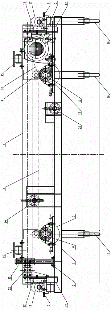
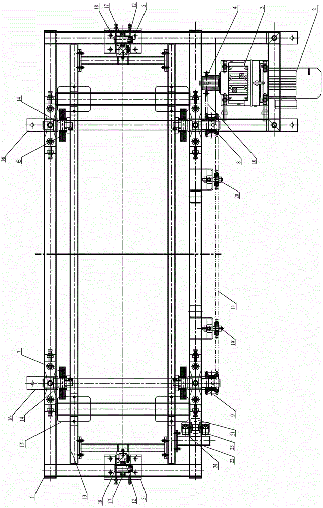
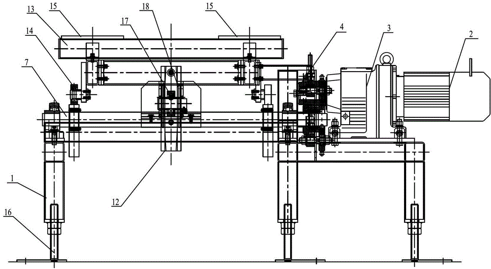
[0014] As shown in the figure: the cam jacking mechanism in the embodiment is mainly composed of a frame 1, a motor 2, a reducer 3, a drive sprocket 4, a guide seat 5, a first camshaft 6, a second camshaft 7, a first chain Wheel 8, second sprocket 9, short chain 10, long chain 11, guide rail 12, lifting frame 13, support wheel 14, workpiece supporting plate 15, adjusting foot 16, guide wheel 17, guide block 18, first sheet Tension pulley 19, the second tension pulley 20, support 21, horn 22, first switch 23 and second switch 24 are composed of components.

[0015] Such as Figure 1~Figure 3 As shown, the motor 2 and the reducer 3 are connected in a conventional manner and are installed together on the frame 1, the drive sprocket 4 is installed on the output shaft of the reducer 3, and the first camshaft 6 is mounted on the frame through a bearing 1 In the bea...


PUM


Abstract

The invention relates to a cam climbing mechanism. A motor and a speed reducer are connected and are installed on a machine frame together, an output shaft of the speed reducer is provided with a driving sprocket, a first cam shaft is installed through a bearing in a bearing bracket which is located at one end of the top of the machine frame, a first sprocket is fixed arranged on the first cam shaft, and a short chain is sleeved on the driving sprocket and the first sprocket. A second cam shaft is arranged in a bearing bracket which is located at the other end of the top of the machine frame through a bearing, a second sprocket is fixedly arranged on the second cam shaft, and a long sprocket is sleeved on the first sprocket and the second sprocket. The lifting frame is placed on the machine frame, and a limit guide mechanism which enables the lifting frame to move in a lifting mode is arranged between the lifting frame and the machine frame. Work piece supporting plates are respectively arranged at two ends of the top of the lifting frame, support wheels are respectively arranged at two ends of the bottom of the lifting frame, and support wheels which are arranged at two ends of the bottom of the lifting frame are respectively arranged on an eccentric cam of the first cam shaft and an eccentric cam of the second cam shaft. The cam climbing mechanism has the advantages of being reasonable in structure, capable of achieving stable ejecting or descending of a tool support, constant in journey, safe and reliable.

Description

technical field [0001] The invention relates to a cam jacking mechanism, in particular to a device for lifting or lowering workpieces from one line body height to another by utilizing eccentric cam transmission, and belongs to the technical field of conveying machinery. Background technique [0002] At present, short-stroke lifting mechanisms generally use cylinders to lift up or down. Since the mechanism is lifted by cylinders on both sides, the extension speed of the cylinders is difficult to adjust, so it is easy to cause the two sides to lift out of sync, and the air pressure is unstable. Under the circumstances, it is easy to make the jacking on both sides asynchronous, causing the body to be unstable when jacking up the car body. At the same time, it is difficult to synchronize the jacking and debugging of the cylinders on both sides, and it is easy to be affected by the unstable air pressure. Contents of the invention [0003] The purpose of the present invention is...

Claims


Application Information

Patent Timeline
Patent Type & Authority Patents(China)
IPC IPC(8): B65G47/52
Inventor 甘玉李锋宝
Owner MIRACLE AUTOMATION ENG CO LTD
Learn More