Support method and device of support pile preformed core-soil double-buttress inclined inner-strut foundation ditch

A technology for reserving core soil and foundation pit support, applied in excavation, foundation structure engineering, construction, etc., can solve the problems of high cost, long construction period, complex construction, etc., achieve convenient material acquisition, improve construction efficiency, and reduce earthwork excavation The effect of digging

Inactive Publication Date: 2013-05-22
XIAMEN YCUCG
View PDF10 Cites 12 Cited by
  • Summary
  • Abstract
  • Description
  • Claims
  • Application Information

AI Technical Summary

Problems solved by technology

[0008] The technical solution described in the above utility model belongs to the horizontal inner

Method used


Image

  • Support method and device of support pile preformed core-soil double-buttress inclined inner-strut foundation ditch
  • Support method and device of support pile preformed core-soil double-buttress inclined inner-strut foundation ditch
  • Support method and device of support pile preformed core-soil double-buttress inclined inner-strut foundation ditch

Examples


Embodiment 1

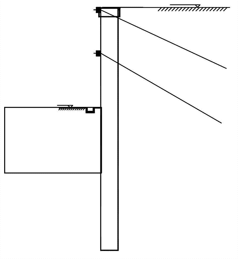
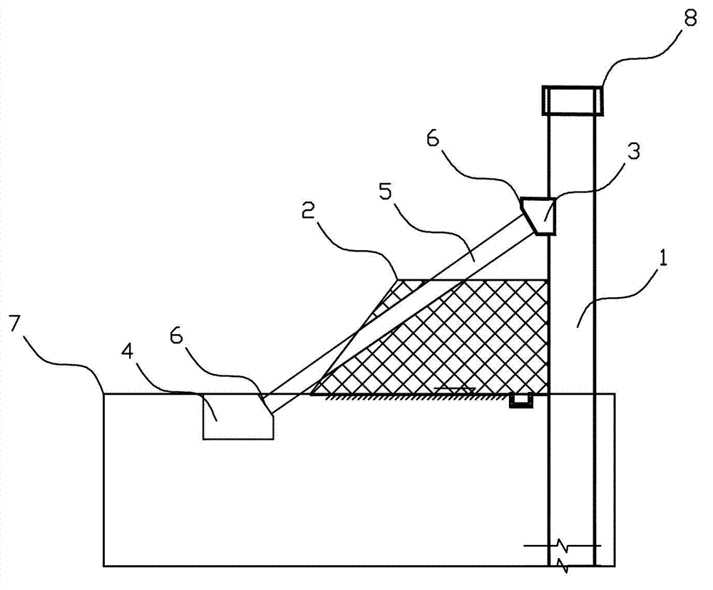
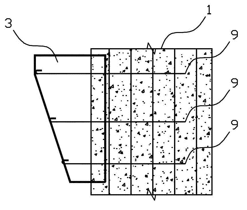
[0042] like figure 2 As shown in the figure, a foundation pit support device with double support pier with reserved core soil includes a support pile 1, and the support pile 1 and the basement floor 7 are provided with a diagonal bracing mechanism. The core soil is reserved near the support pile 1. The diagonal bracing mechanism is as follows: a pile body buttress 3 is buried in the support pile 1 body, a bottom plate buttress 4 is buried in the basement floor 7, and a diagonal brace beam 5 is diagonally braced between the pile body buttress 3 and the bottom plate buttress 4.

[0043] The support pile 1 is a support body that resists the load outside the foundation pit. The strength of the support pile 1 must meet the requirements for supporting the load of the foundation pit. It can be a reinforced concrete structure or a steel structure, using traditional cast-in-place piles or steel piles as support Structural retaining body.

[0044] Core soil 2 is the undisturbed soil ...

Embodiment 2

[0051]This embodiment is an implementation with caps. Preferably, the diagonal brace angle of the section steel is in the range of 50°-55° to meet the requirements. In this embodiment, the diagonal brace angle is 50°.

[0052] In actual construction, the complete steps are as follows:

[0053] The first step: construction of support pile 1

[0054] The second step: crown beam 8 construction

[0055] Step 3: Excavate the earth layer by layer to the pier 3 of the pile body, and carry out the construction of the pier 3 of the pile body;

[0056] Step 4: Excavate the earth in layers and sections, and leave the core soil 2;

[0057] Step 5: Pour and tamp construction of floor support pier 4;

[0058] Step 6: The diagonal brace beam 5 is hoisted in place and welded firmly with the steel plate 6 of the pile body support pier 3 and the bottom plate support pier 4;

[0059] Step 7: Construction of basement floor 7 and shear wall, backfilling of earthwork and pouring and tamping of ...


PUM

PropertyMeasurementUnit
Lengthaaaaaaaaaa

Abstract

The invention relates to a support method of a support pile preformed core-soil double-buttress inclined inner-strut foundation ditch. An inclined strut mechanism is arranged between a support pile and a basement floor, core-soil is reserved in the position in the foundation ditch which is arranged on one side of the inclined strut mechanism, and the position is close to the support pile. A device of the support pile preformed core-soil double-buttress inclined inner-strut foundation ditch comprises a support pile, the inclined strut mechanism is arranged between the support pile and the basement floor, core-soil is reserved at the position in the foundation ditch which is arranged on one side of the inclined strut mechanism, and the position is close to the support pile. The method and the device of the support pile preformed core-soil double-buttress inclined inner-strut foundation ditch are suitable for geological conditions that an unknown cable, a pipe ditch or a cave exist in surrounding geology and geological conditions which are not suitable for utilizing ditch support of a piled anchor or a cantilever and a horizontal strut of anchor cable construction and the like and are convenient to construct and short in a project schedule.

Description

technical field [0001] The invention relates to the technical field of foundation pit support construction in civil engineering, and more specifically, relates to a method and device for supporting a foundation pit with a double-support pier inclined inner support with core soil reserved for support piles. Background technique [0002] Foundation pit support is an important issue that must be faced in the basement construction of important, large or extra large buildings at home and abroad. The currently commonly used technical solution is grading + pile-anchor system (such as figure 1 As shown), or cantilever support + horizontal inner support, for the foundation pit with poor surrounding soil quality or surrounding soil with stones or pipelines, the above methods are not suitable, and there are great difficulties in setting up foundation pit support. [0003] Analysis and research and physical evidence prove that for the pile-anchor quality, the construction quality of th...

Claims


Application Information

Patent Timeline
IPC IPC(8): E02D17/04
Inventor 杨克红陈德华李丕景廖建漳
Owner XIAMEN YCUCG
Why Eureka
Try Eureka