Coupling-type wind driven generator

A wind power generator, coupled technology, applied in wind power generators, wind power motor combinations, wind power generators at right angles to the wind direction, etc., can solve problems such as high blade quality requirements, low energy conversion rate, and too large blades, etc., to achieve Improve the wind energy utilization rate, improve the energy conversion rate, and reduce the volume of the whole machine

Inactive Publication Date: 2013-05-22
JIANGSU ZHONGYUN WIND POWER SCIENCE & TECHNOLOGY CO LTD
View PDF10 Cites 4 Cited by
  • Summary
  • Abstract
  • Description
  • Claims
  • Application Information

AI Technical Summary

Problems solved by technology

Due to the centrifugal blade arrangement and the high velocity of the wind when it enters the engine inlet, in order to convert the powerful wind energy into mechanical energy, the quality of the blades is high and the weight will be heavy. As a result, it is difficult to start at low wind speeds.
In addition, when the upper-stage fan rotates, the synchronization of the tail wind entering the lower stage is poor, which will affect each other. When the blades do work, due to a lot of turbulent flow, the energy loss is serious
Secondly, the multi-stage series connection of the central shaft will also cause the shaft to be too long and heavy, so that the concentricity is difficult to guarantee, the output torque will be affected, and the energy conversion rate will be reduced.
Furthermore, because the blades are too large, there are big problems in design and manufacture, material synthesis, transportation, installation, maintenance, etc.

Method used


Image

  • Coupling-type wind driven generator
  • Coupling-type wind driven generator

Examples


Embodiment Construction

[0013] Below in conjunction with accompanying drawing, the present invention is described in further detail:

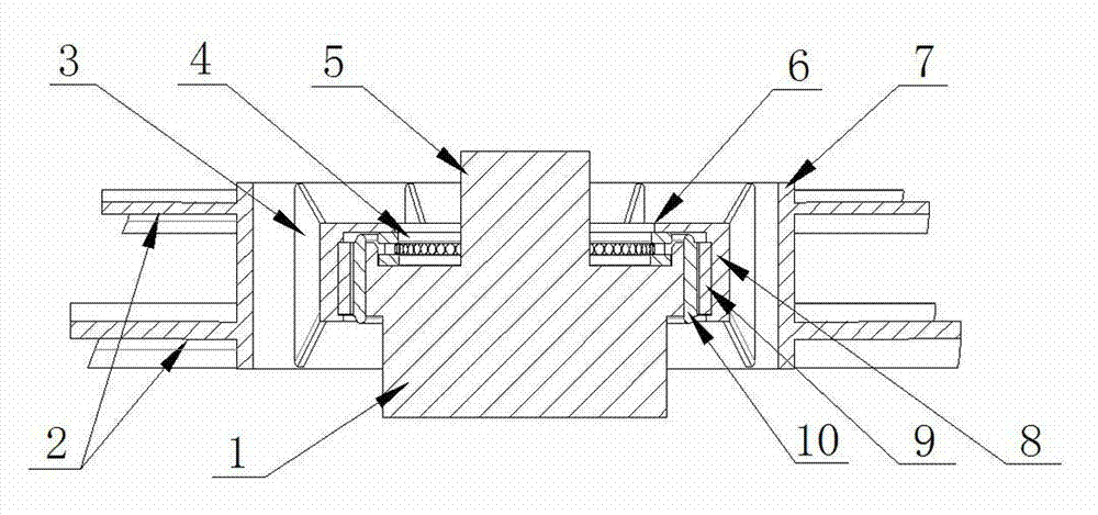
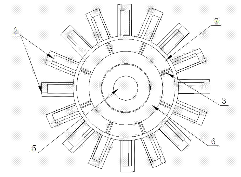
[0014] Such as figure 1 and figure 2 As shown, the coupled wind power generator of the present invention includes a base column 1 which is arranged vertically and has a support shaft 5 at the center of its upper end surface. A wheel hub 7 is sheathed on the support shaft 5, and the outer surface of the wheel hub 7 is evenly distributed with turbine blades 2 along the circumferential direction, and the inclination directions of the turbine blades 2 are all the same. There is a spoke 6 at one end of the axial direction of the hub 7, and the spoke 6 can be a complete circular plate, or a fancy spoke like an automobile hub, but the central position must have a circle for being sleeved on the supporting shaft 5. Holes, the spoke 6 of the present embodiment is a disc with a central hole. There is a thrust cylindrical roller bearing 4 between the upper end surface of the...


PUM


Abstract

The invention relates to a coupling-type wind driven generator. The coupling-type wind driven generator is characterized by comprising a base pillar, wherein the base pillar is vertically arranged, and a supporting shaft is arranged at the center of the upper end face of the base pillar. A wheel hub is sleeved on the supporting shaft, and turbine blades are evenly distributed on the outer surface of the wheel hub along the circumferential direction. A spoke is arranged at one axial end of the wheel hub, the wheel hub is supported on the upper end face of the base pillar through the spoke, and the wheel hub is rotatably matched with the supporting shaft. A generator rotor is fixed on the inner side of the wheel hub, a generator stator is fixed on the section, in the wheel hub, of the supporting shaft or on the outer wall of the base pillar, the positions of the generator rotor and the generator stator are corresponding, and the inner diameter of the generator rotor is larger than the outer diameter of the generator stator. The generator is used in matching with an annular wind gathering air channel, on the premise of meeting the requirement of high power, the length of the blade can be effectively shortened, the size of the whole generator is effectively reduced, and the use rate of the wind energy can be improved.

Description

technical field [0001] The invention relates to a wind power generator, specifically a coupled wind power generator that integrates the generator stator / rotor and the wind wheel, which is especially suitable for being installed in an annular air duct for wind power generation, especially the annular wind gathering wind turbine. Tao usage occasions. Background technique [0002] As we all know, in order to reduce the excessive development and utilization of natural resources, countries all over the world pay more attention to the use of wind power to generate electricity. Traditional wind turbines are divided into two categories: horizontal axis and vertical axis. High-power wind turbines are mainly based on the horizontal axis. In order to increase the sweeping area as much as possible, the wind rotor blades of this type of generator often have It is very large, usually the length of a single blade is 60 meters, and the weight reaches about 8 tons, which brings great dif...

Claims


Application Information

Patent Timeline
Patent Type & Authority Applications(China)
IPC IPC(8): F03D9/00F03D3/06
CPCY02E10/74
Inventor 李勇强谢玉琪杨伟涛张红旭宋林森
Owner JIANGSU ZHONGYUN WIND POWER SCIENCE & TECHNOLOGY CO LTD
Why Eureka
Try Eureka