Optical fiber Fabry-Perot sensor multiplexing method and device based on multi-wavelength and low-coherence light source

A method of Faber sensor and multiplexing device, applied in the field of fiber Faber sensor multiplexing method and device, to achieve the effect of not affecting demodulation accuracy and stability, reducing cost, and independent demodulation

Active Publication Date: 2013-05-22
TIANJIN UNIV
View PDF4 Cites 14 Cited by
  • Summary
  • Abstract
  • Description
  • Claims
  • Application Information

AI Technical Summary

Problems solved by technology

However, the above multiplexing method will no longer be applicable to the case where the optical fiber F-P sensors have the same cavity length, or there is overlap in the process of changing the cavity length

Method used


Image

  • Optical fiber Fabry-Perot sensor multiplexing method and device based on multi-wavelength and low-coherence light source
  • Optical fiber Fabry-Perot sensor multiplexing method and device based on multi-wavelength and low-coherence light source
  • Optical fiber Fabry-Perot sensor multiplexing method and device based on multi-wavelength and low-coherence light source

Examples


Embodiment 1

[0027] Example 1: Multiplexing device for optical fiber F-P sensor based on multi-wavelength low-coherence light source

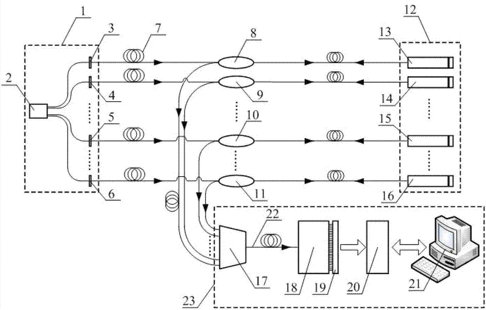
[0028] The device consists of a light source module, a 3dB coupler, a fiber optic sensor, a multi-channel beam combiner, a demodulation interferometer, a photoelectric conversion device, an acquisition card, and a computer. Multimode optical fibers are used between the components of the optical path for optical signal transmission. :

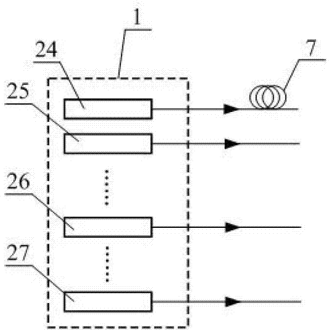
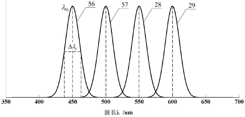
[0029] The light source module 1 is composed of a broadband light source 2 and N first and second filters of different wavelengths...i-th filter and N-th filter, and the light emitted by the broadband light source 2 is coupled into N multimode optical fibers 7 at the same time , N represents the total number of multiplexing channels of the optical fiber Fab sensor. The broadband light of the i-th channel (i represents a number between 1 and N) passes through the i-th optical filter, and outputs low-coherent light with a wavele...

Embodiment 2

[0039] Example 2: Superposition analysis of low-coherence interference signals generated by multi-wavelength low-coherence light sources

[0040] Low-coherence interference refers to the use of a short coherence length light source to generate interference. It has the characteristics of the maximum interference fringe visibility when the optical path difference is zero, and with the increase and decrease of the optical path difference, the interference fringe visibility gradually decays. When the optical path difference is greater than the coherence length of the light source, the interference fringe visibility will be zero. It can be concluded that when the optical path difference is zero, it corresponds to the low coherence interference fringe envelope peak. This conclusion is based on low-coherence interferometry.

[0041] The multiplexing method of the present invention will be analyzed in detail below by taking the multiplexing of the four-channel optical fiber F-P senso...

Embodiment 3

[0047] Embodiment 3: Multiplexing method of optical fiber Fab sensor based on multi-wavelength low-coherence light source

[0048] The reflected light signals of the sensors of each channel are synthesized into a beam of light by the multi-channel beam combiner 17, and after being incident on the demodulation interferometer 18, the superposition result 38 of low-coherence interference fringes is output. The normalized light intensity function of superimposed low-coherence interference fringes is expressed as:

[0049] I ( λ , t ) = Σ i = 1 4 ∫ - ∞ + ∞ S i ( λ ) · I i ...


PUM


Abstract

The invention discloses an optical fiber Fabry-Perot sensor multiplexing method and device based on a multi-wavelength and low-coherence light source. The optical fiber Fabry-Perot sensor multiplexing device comprises a light source module, 3dB couplers, an optical fiber Fabry-Perot sensor unit and a demodulation unit. The optical fiber Fabry-Perot sensor multiplexing method is characterized in that all channels of the light source module output low-coherence light with different wavelengths; N channel light passes through the corresponding 3dB couplers and then are irradiated to the corresponding optical fiber Fabry-Perot sensors, and reflected light re-passes the corresponding 3dB couplers and form a light beam through a multi-channel beam combiner to be irradiated into the demodulation unit; a demodulation interferometer achieves optical path difference scanning and outputs low-coherence interference fringes overlapped with all sensor cavity length information; and low-coherence interference fringe optical signals are converted to electric signals and then transmitted to a computer, the signals are subjected to filter analysis and decision algorithm processing, simultaneously all optical fiber Fabry-Perot sensor information is demodulated, and multiplexing of the optical fiber Fabry-Perot sensor is achieved. Compared with the prior art, the optical fiber Fabry-Perot sensor multiplexing method and device reduce system cost, support batch production, and can simultaneously and independently achieve multi-channel sensor multiplexing demodulation.

Description

technical field [0001] The invention relates to the field of optical fiber sensing, in particular to a method and device for multiplexing an optical fiber Fab sensor. Background technique [0002] The optical fiber F-P sensor uses the change of the F-P cavity length to realize the sensing and measurement of physical quantities such as displacement, pressure and temperature. Due to its advantages of small size, high precision and good stability, it has attracted extensive attention in both research and application fields. However, compared with other fiber optic sensors such as fiber gratings, the technology used by the Fap sensor to realize the multiplexing of multi-point simultaneous sensing and measurement is more complicated. [0003] The multiplexing method of optical fiber F-P sensor can be roughly divided into two categories, one is the optical path difference scanning method, and its principle is to use the optical path difference scanning method to match the cavity l...

Claims


Application Information

Patent Timeline
Patent Type & Authority Applications(China)
IPC IPC(8): G01D5/353
Inventor 江俊峰刘铁根尹金德刘琨王双吴凡秦尊琪宋璐瑶
Owner TIANJIN UNIV
Why Eureka
Try Eureka