Direct dynamic force measurement device of shock-wave-loaded double-raw model sphere array

A measuring device and dynamic force technology, applied in the analysis of materials, instruments, etc., can solve the problems that the gas phase parameters cannot be accurately controlled and measured, and the influence of the particle group spatial arrangement shock wave and the interference of the wake vortex structure cannot be reasonably considered, and achieve Effect of good experimental setup and test method

Inactive Publication Date: 2013-05-22
ZHEJIANG SCI-TECH UNIV
View PDF3 Cites 8 Cited by
  • Summary
  • Abstract
  • Description
  • Claims
  • Application Information

AI Technical Summary

Problems solved by technology

The predecessors used shock tube wind tunnels to generate shock waves. One is based on optical methods, that is, using high-speed photography technology to obtain moving images of particle groups driven by shock waves and airflow after the waves, and obtain velocity and acceleration data to determine the force on particle groups. , its main defect is that the gas phase parameters cannot be precisely controlled and measured; the second is to carry out direct measurement of effective resistance for a single sphere or several sphere models, and its main defect is that it cannot reasonably consider the spatial arrangement of particle groups or the shock wave of adjacent particles Effects of interference with wake vortex structures

Method used


Image

  • Direct dynamic force measurement device of shock-wave-loaded double-raw model sphere array
  • Direct dynamic force measurement device of shock-wave-loaded double-raw model sphere array
  • Direct dynamic force measurement device of shock-wave-loaded double-raw model sphere array

Examples


Embodiment Construction

[0018] The present invention will be further described below in conjunction with accompanying drawings and examples.

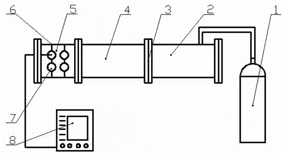
[0019] like figure 1 As shown, it includes a high-pressure air source 1, a driving section 2, a diaphragm 3, a driven section 4, a test section 5, a wire 6, a model ball 7 and a high-speed data acquisition system 8; one end of the driving section 2 and the driven section 4 One end of the diaphragm 3 is connected to form a shock tube, the high-pressure gas source 1 is connected to the other end of the driving section 2, one end of the test section 5 is connected to the other end of the driven section 4, and the acceleration in the model ball 7 in the test section 5 Meter sensor 12 leads are connected with high-speed data acquisition system 8.

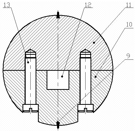
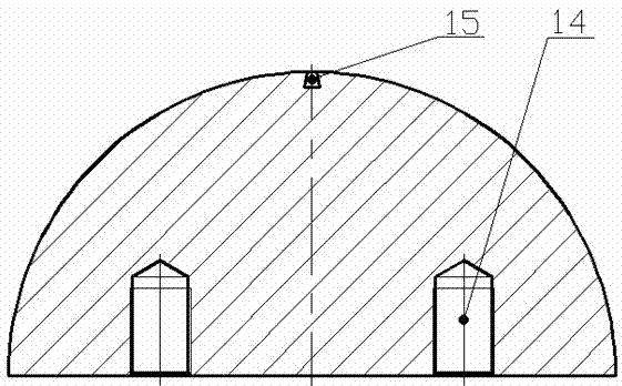
[0020] like figure 2 , image 3 , Figure 4 , Figure 5 , Image 6 As shown, two rows of equidistantly distributed small holes 18 are arranged on the axial cylindrical surface of the test section 5, and the same r...


PUM


Abstract

The invention discloses a direct dynamic force measurement device of a shock-wave-loaded double-raw model sphere array. The direct dynamic force measurement device comprises a high-pressure air source, a driving section, a diaphragm, a driven section, a tested section, a metal wire, model spheres and a high-speed data acquisition system, wherein one end of the driving section and one end of the driven section are connected by the diaphragm to form a shock tube; the high-pressure air source is connected with the other end of the driving section; one end of the tested section is connected with the other end of the driven section; and lead wires of accelerometer sensors in the model spheres inside the tested section are connected with the high-speed data acquisition system. According to the direct dynamic force measurement device disclosed by the invention, the tested section, which is a transparent organic glass pipe, can be used for carrying out optical measurement; different model sphere arrays needed by experiments can be formed by accurately controlling the number, distribution and spacing of the model spheres because the tested section is provided with double rows of holes and 36 small holes are uniformly distributed in the same radial sections of each row of holes; and the direct measurement on the dynamic force of a shock-wave-loaded granule group is realized by the accelerometer sensors and the high-speed data acquisition system. According to the invention, a good experimental device and testing method are provided for subsequent research.

Description

technical field [0001] The invention relates to a dynamic force direct measurement device, in particular to a shock wave-loaded dynamic force direct measurement device of a double-row model ball array. Background technique [0002] The interaction between shock waves and solid particles generally exists in supersonic gas-solid two-phase flow, involving many fields such as medical and health care, clean energy, material surface treatment, safety prevention and control, and aerospace. Supersonic separation of dust and gas, pulse powder fire extinguisher, supersonic cold spraying, solid fuel booster nozzle, etc. One of the key scientific issues in the study of shock-induced gas-solid two-phase flow is to reveal the interaction mechanism between the shock wave and the solid particle group, and to grasp the dynamic force of the shock-loaded particle group, and experimental research is the key to solving this problem. One of the effective means, which relies on the specially des...

Claims


Application Information

Patent Timeline
Patent Type & Authority Applications(China)
IPC IPC(8): G01N15/00
Inventor 章利特黄保乾陈婉君施红辉亓洪训张苹
Owner ZHEJIANG SCI-TECH UNIV
Why Eureka
Try Eureka