Circuit and method for detecting voltage peak

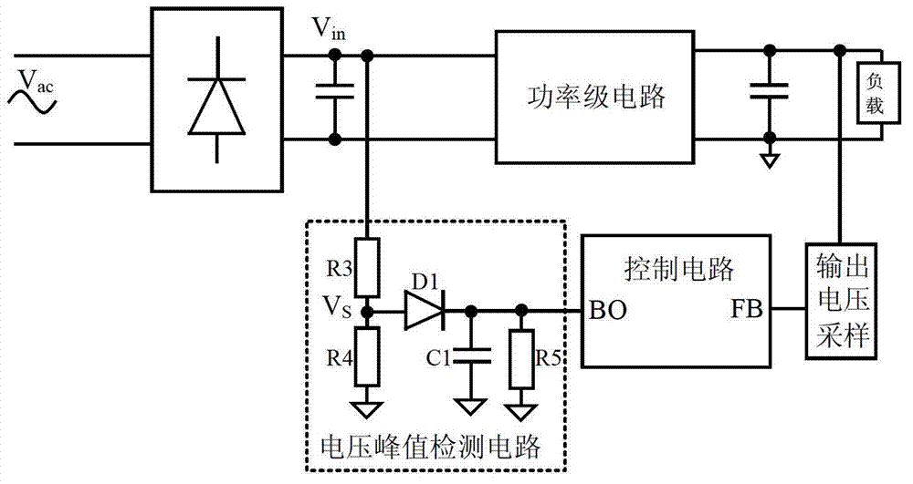
A voltage peak, detection circuit technology, applied in the direction of AC/pulse peak measurement, current/voltage measurement, measurement device, etc., can solve the problems of unfavorable circuit integration design, large resistance value of resistor R5, large volume cost, etc., and achieve loss Small, low cost, good for integration

Active Publication Date: 2013-05-22
SILERGY SEMICON TECH (HANGZHOU) CO LTD
View PDF6 Cites 27 Cited by
  • Summary
  • Abstract
  • Description
  • Claims
  • Application Information

AI Technical Summary

Problems solved by technology

[0006] It can be seen that the resistance value of the resistor R5 is very large, both...

Method used


Image

  • Circuit and method for detecting voltage peak
  • Circuit and method for detecting voltage peak
  • Circuit and method for detecting voltage peak

Examples


Embodiment Construction

[0049] Several preferred embodiments of the present invention will be described in detail below with reference to the accompanying drawings, but the present invention is not limited to these embodiments. The present invention covers any alternatives, modifications, equivalent methods and schemes made on the spirit and scope of the present invention. In order to provide the public with a thorough understanding of the present invention, specific details are set forth in the following preferred embodiments of the present invention, but those skilled in the art can fully understand the present invention without the description of these details.

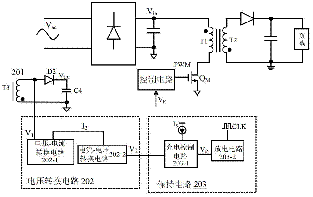
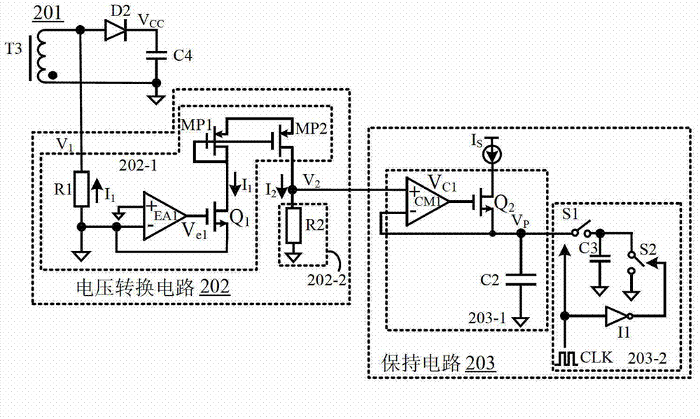
[0050] refer to figure 2, is shown as a circuit block diagram of an embodiment of a voltage peak detection circuit according to the present invention; the voltage peak detection circuit is applied to a switching power supply. In this embodiment, a flyback switching power supply is taken as an example, and its power stage There is a tran...


PUM


Abstract

The invention discloses a circuit and a method for detecting a voltage peak. Input voltage information is acquired in a coupling manner by a voltage coupling circuit instead of being sampled by directly connecting a power level circuit, on one hand, the number of pins of a chip can be decreased, and on the other hand, loss can be reduced and efficiency can be improved without a sampling resistor or the like. Besides, first voltage outputted to the voltage coupling circuit by a voltage conversion circuit and a holding circuit is used for conversion and holding, and a peak voltage signal representing direct-current input voltage of a switching power supply can be obtained and used by a follow-up circuit. Components such as a large resistor and a large capacitor are omitted, and compared with the prior art, the circuit and the method for detecting the voltage peak have the advantages that cost is greatly reduced, the size is small, and circuit integration is facilitated.

Description

technical field [0001] The invention relates to the field of power electronics, and more specifically, to a voltage peak detection circuit and a detection method. Background technique [0002] In the power switching circuit, it is often necessary to detect the peak value of the input voltage signal and save it for use in the subsequent control circuit. Generally speaking, the peak detection circuit is required to be able to respond to the input voltage signal and give its accurate peak information. [0003] Such as figure 1 Shown is a circuit diagram of a voltage peak detection circuit in the prior art, which is applied to a switching power supply. It samples the DC input voltage signal of the switching power supply through the voltage dividing resistor network R3 and R4, and obtains a characteristic DC input voltage signal V in When the voltage signal Vs is less than the voltage across the capacitor C1 and the diode D1 cannot be turned on, the capacitor C1 is discharged t...

Claims


Application Information

Patent Timeline
IPC IPC(8): G01R19/04H02M1/00
CPCG01R19/165H02M7/2176G01R19/04H02M1/0022H02M3/33507
Inventor 徐孝如
Owner SILERGY SEMICON TECH (HANGZHOU) CO LTD
Why Eureka
Try Eureka