Method and device for analyzing vector signals

A vector signal and analysis method technology, applied in the field of vector signal analysis, can solve the problems of difficult control of module delay, difficult to eliminate DDS spurs, difficult to implement, etc.

Active Publication Date: 2013-05-22
CHINA ELECTRONIS TECH INSTR CO LTD
View PDF4 Cites 16 Cited by
  • Summary
  • Abstract
  • Description
  • Claims
  • Application Information

AI Technical Summary

Problems solved by technology

At present, the clock generator that realizes high frequency, high precision, and wide range can be realized by a fractional N frequency synthesizer based on Σ-Δ modulation noise shaping technology. This method has high technical requirements and is difficult to implement; another method is to use DDS (Direct Digital Frequency Synthesis, direct digital frequency synthesis) technology to achieve, the method is simple, but DDS spurs are difficult to eli...

Method used


Image

  • Method and device for analyzing vector signals
  • Method and device for analyzing vector signals
  • Method and device for analyzing vector signals

Examples


no. 1 example

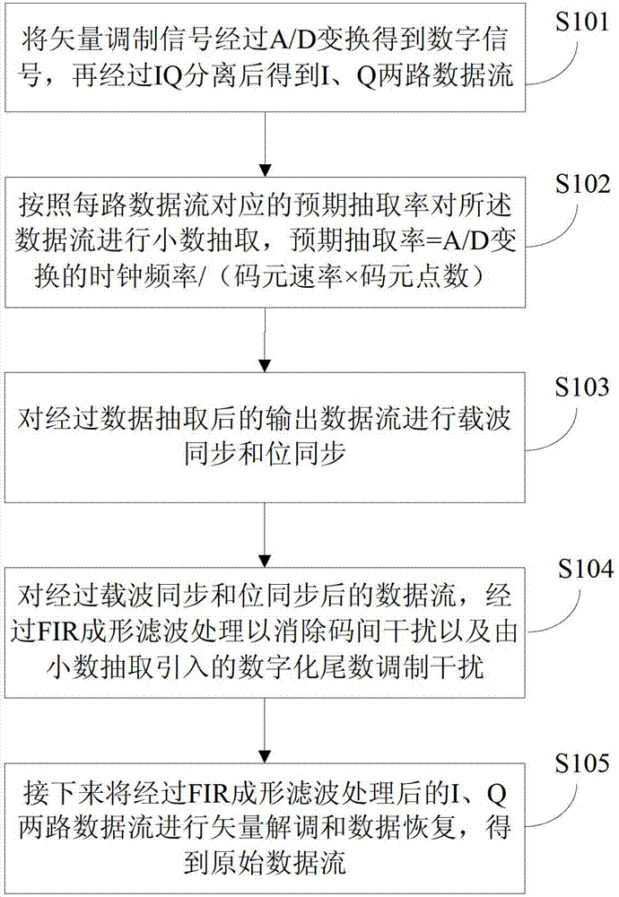
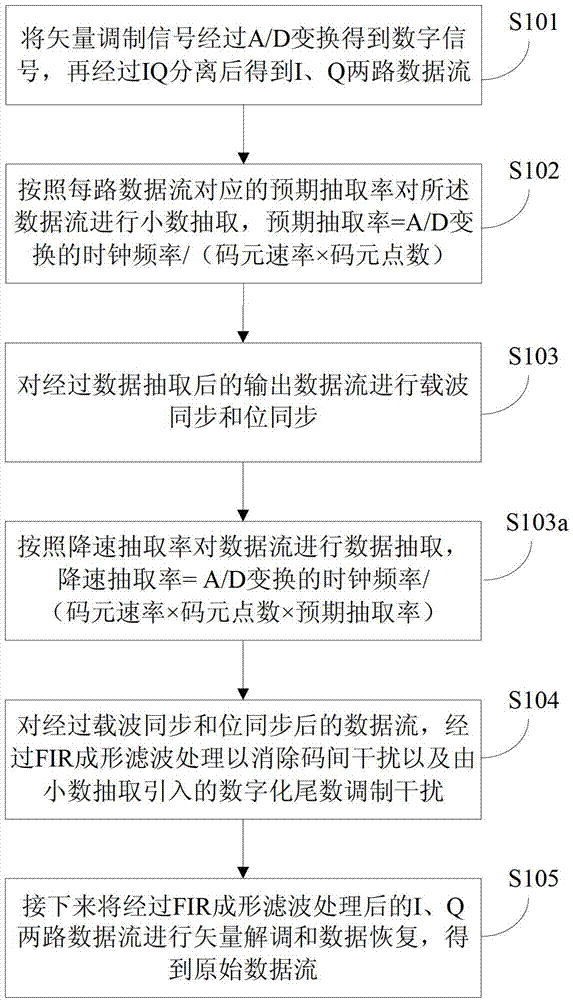
[0048] In the first embodiment of the present invention, a vector signal analysis method, such as figure 1 shown, including the following steps:

[0049] In step S101, the vector modulation signal is subjected to A / D conversion to obtain a digital signal, and then IQ separation is performed to obtain two data streams of I and Q.

[0050] Step S102, perform decimal extraction on the data stream according to the expected extraction rate corresponding to each data stream, the expected extraction rate=clock frequency of A / D conversion / (symbol rate×number of symbol points), and output the data stream after extraction The rate is an integer multiple of the product of the symbol rate of the vector modulation signal and the number of symbol points.

[0051] Specifically, based on the expected decimation rate corresponding to the data stream, the sigma-delta modulation conversion method is used to obtain the decimation rate of the data stream in each A / D conversion clock cycle, and th...

no. 2 example

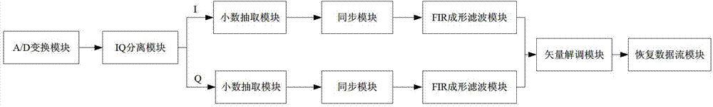
[0066] In the second embodiment of the present invention, a vector signal analysis device, such as image 3 As shown, including: A / D conversion module, IQ separation module, decimal extraction module, synchronization module, FIR shaping filter module, vector demodulation module and recovery data stream module, wherein,

[0067] The vector modulation signal passes through the A / D conversion module to form a digital signal, and then passes through the IQ separation module to obtain two data streams of I and Q;

[0068] The decimal extraction module performs decimal extraction on the data stream according to the expected extraction rate corresponding to each data stream, the expected extraction rate=clock frequency of A / D conversion / (symbol rate×number of symbol points), and output data after decimal extraction The rate of the stream is an integer multiple of the product of the symbol rate of the vector modulation signal and the number of points per symbol; the output data stream...


PUM


Abstract

The invention discloses a method and a device for analyzing vector signals. The method includes digitalizing vector modulating signals by means of A/D (analog/digital) conversion for fixed sampling; converting data rates via a decimal extraction module on the basis of the Sigma-delta modulation conversion shaping technology; resampling data; enabling each data rate to be equal to integer multiples of a symbol rate and the number of symbol points; eliminating inter-code interference and digital mantissa modulation jamming by the aid of FIR (finite impulse response) shaping filter; and performing vector demodulation and data restoration to obtain received original information. The digital mantissa modulation jamming is caused by Sigma-delta modulation conversion. The method and the device have the advantages that sampling rates are converted by the Sigma-delta modulation conversion shaping technology, vector modulation signals at different symbol rates can be received, the quality of the signals can be analyzed, and the performance of a receiver is improved.

Description

technical field [0001] The present invention relates to the technical field of signal analysis of communication systems, in particular to a vector signal analysis method and device. Background technique [0002] In a receiver with multiple modulation formats and a wide range of symbol rates, configurable and programmable hardware devices are required for receiving modulated signals with different symbol rates. Generally, a variable high sampling frequency A / D (analog to digital) conversion is used, so that the sampling data is an integer multiple of the symbol rate multiplied by the number of points per symbol. Then through the decimation filter, the rate is reduced to the symbol rate multiplied by the number of each symbol point, and then it is filtered and shaped by FIR, and finally sent to the software for analysis to calculate the received original information. This method has high requirements on hardware, and requires a high-frequency, high-precision, wide-range clock...

Claims


Application Information

Patent Timeline
IPC IPC(8): H04L27/00
Inventor 凌云志
Owner CHINA ELECTRONIS TECH INSTR CO LTD
Why Eureka
Try Eureka