Manually-pressed type rotating mop rod

A rotary mop, hand-pressing technology, applied in the direction of cleaning carpets, floors, household appliances, etc., can solve the problems of laborious pull-up process, amplifying sliding sound, easy wear of transmission teeth, etc., to achieve easy pull-up or push-down , The effect of reducing the contact area and increasing the rotation speed

Active Publication Date: 2013-05-29
浙江美添乐家居用品股份有限公司
View PDF7 Cites 22 Cited by
  • Summary
  • Abstract
  • Description
  • Claims
  • Application Information

AI Technical Summary

Problems solved by technology

In this technical solution, during the pull-up process, the screw rod moves upward, and the rotating sleeve forms an idle rotation driven by the screw rod. During the rotation, the sliding surfaces of the two transmission teeth conflict with each other, resulting in friction, and the pull-up process is laborious. After a long time of use, the transmission teeth are easy to wear, resulting in idling when pressing down, which affects the use; moreover, the two transmission teeth slide against each other, and the sliding sound during the pull-up process is amplified between the inner and outer rods, resulting in noise
[0004] In the above technical solution, there are many parts and the assembly process is relatively complicated, and the transmission is realized by the cooperation between the screw rod and the screw teeth in the rotating sleeve, that is, the cooperation between the screw and the screw is adopted, and the contact area between the two is relatively

Method used


Image

  • Manually-pressed type rotating mop rod
  • Manually-pressed type rotating mop rod
  • Manually-pressed type rotating mop rod

Examples


Embodiment Construction

[0021] In order to enable those skilled in the art to better understand the solutions of the present invention, the technical solutions in the embodiments of the present invention will be clearly and completely described below in conjunction with the drawings in the embodiments of the present invention.

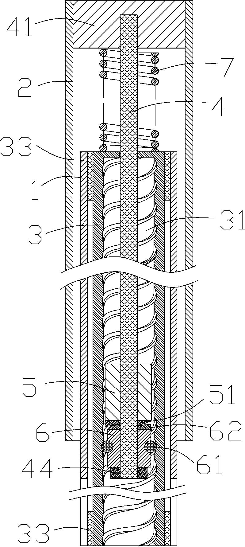
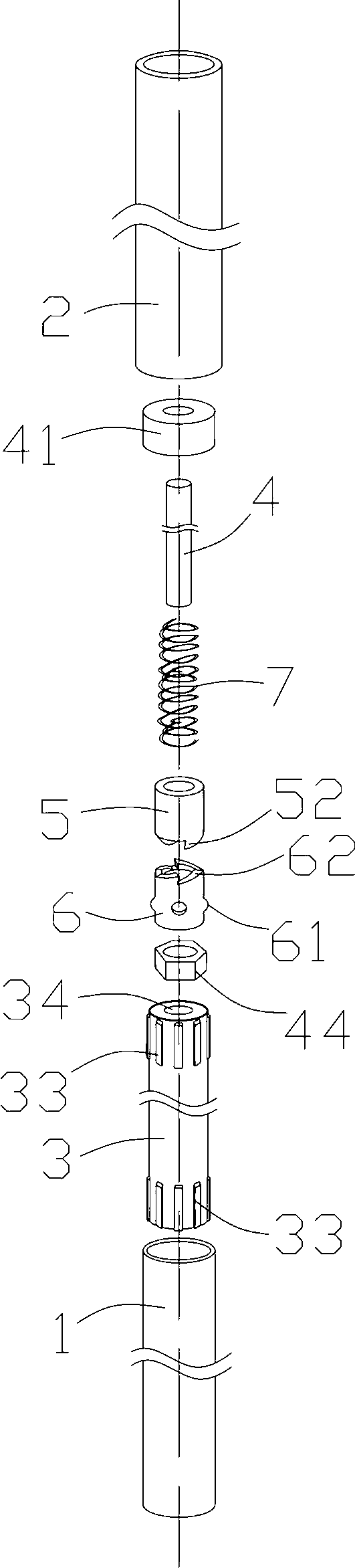
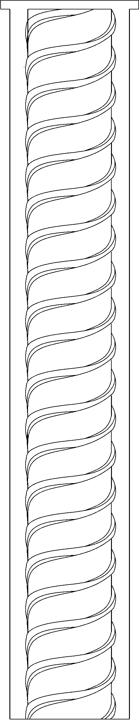
[0022] Such as figure 1 As shown, a hand-pressed rotary mop rod includes the following parts: an inner rod body 1 and an outer rod body 2 that are socketed with each other, and the lower end of one of the inner and outer rods is connected to the mop head. In this embodiment, the inner rod body is used The lower end is connected to the mop head; the rotating sleeve 3 arranged on the inner rod body 1 is fixedly connected between the outer wall of the rotating sleeve and the inner wall of the inner rod body 2, and the inner wall of the rotating sleeve 3 is provided with a spiral groove 31; The guide shaft core 4 inside the sleeve 3 and whose upper end is fixedly connected with t...


PUM


Abstract

The invention discloses a manually-pressed type rotating mop rod. The manually-pressed type rotating mop rod comprises an inner rod body, an outer rod body, a rotating sleeve, a guide shaft core, a rotating guide piece, a blocking portion and a braking portion. The inner rod body and the outer rod body are mutually connected in a sleeved mode. The rotating sleeve is arranged in the inner rod body and the inner wall of the rotating sleeve is provided with a spiral groove. The guide shaft core is arranged in the rotating sleeve, and the upper end of the guide shaft core is fixedly connected with the outer rod body. The rotating guide piece is sleeved at the lower end of the guide shaft core and capable of rotating along the guide shaft core. The blocking portion is arranged at the lower end of the guide shaft core and used for blocking the rotating guide piece from slipping off. The braking portion is capable of preventing the rotating guide piece from rotating. The rotating guide piece is capable of moving vertically in a small distance between the blocking portion and the braking portion. The manually-pressed type rotating mop rod is simple in structure, small in number of components, easy to assemble and high in production efficiency, and dewatering effect is improved greatly, and the phenomenon that a mop head idles can not happen in long-term use.

Description

technical field [0001] The invention relates to the field of mop manufacture, in particular to a hand-pressed rotary mop rod. Background technique [0002] After the mop is cleaned, the wiping material at the end needs to be wrung out. The traditional way is to wring it out manually, which is laborious. Some mechanically wrung mops have also appeared in recent years, as described in Chinese patent application CN101828893, which discloses a mop and its matching mop bucket as there are more on the market at present. In this technical solution, the mop The rod includes inner and outer rods that are nested with each other, a screw rod member and a rotating sleeve sleeved on the screw rod member. The screw teeth or openings that match the screw rod member are arranged in the rotating sleeve, and a ring is provided on the outer periphery of the rotating sleeve. The transmission sleeve matched with its one-way transmission, the outer wall of the transmission sleeve is fixedly conn...

Claims


Application Information

Patent Timeline
IPC IPC(8): A47L13/20A47L13/58
Inventor 童弋康林辉
Owner 浙江美添乐家居用品股份有限公司
Why Eureka
Try Eureka