Check patentability & draft patents in minutes with Patsnap Eureka AI!

Mold and method for sectionally adjusting cooling efficiency of the mold

A mold cooling and segmentation technology, which is applied in the direction of forming tools, manufacturing tools, metal processing equipment, etc., can solve problems such as uneven cooling, limited mold shape design, and inability to form mechanical products.

Inactive Publication Date: 2013-05-29
METAL INDS RES & DEV CENT
View PDF5 Cites 6 Cited by
  • Summary
  • Abstract
  • Description
  • Claims
  • Application Information

AI Technical Summary

Problems solved by technology

[0004] The conventional cooling channel layout only considers the heat dissipation of the mold base, and does not make detailed calculations for the uniform heat conduction during or after stamping and improve the design of the cooling channel structure, resulting in uneven mechanical properties of the finished product or even deformation and fracture
[0005] The prior art provides a method of changing the cooling rate by changing the water volume, the size of the metal mold, etc. By controlling the cooling rate of the mold, the problem of steel plate damage due to the cooling rate of the steel plate being too fast can be solved
However, it is too time-consuming and labor-intensive to calculate the metal mold size for the cooling rate every time a mold is made, and the above method cannot be used to form products with more than two mechanical properties
[0006] In view of the limitation that the drilling method can only drill straight holes, the distance between the cooling pipe and the surface of the concave and convex mold is not equal, which will inevitably cause uneven cooling. The previous technology provides a hot stamping forming mold, in which the vertical height is used Equal cooling channels to solve the problem that the mold is difficult to cool uniformly and the surface shape of the mold is difficult to open.
The above-mentioned prior art mentions that cooling ducts with different widths and the arrangement of multiple cooling ducts can be used to ensure the mechanical strength of the mold, but the above-mentioned method makes the configuration of the cooling duct more complicated, and the above-mentioned method cannot be used to form a mold with two cooling ducts. Products with more than one mechanical property
In addition, limited by the mold shape design, sometimes it is not feasible to increase the density of cooling channels

Method used


Image

  • Mold and method for sectionally adjusting cooling efficiency of the mold
  • Mold and method for sectionally adjusting cooling efficiency of the mold
  • Mold and method for sectionally adjusting cooling efficiency of the mold

Examples


Embodiment

[0037] 1. A method for controlling the mold cooling rate in sections, comprising:

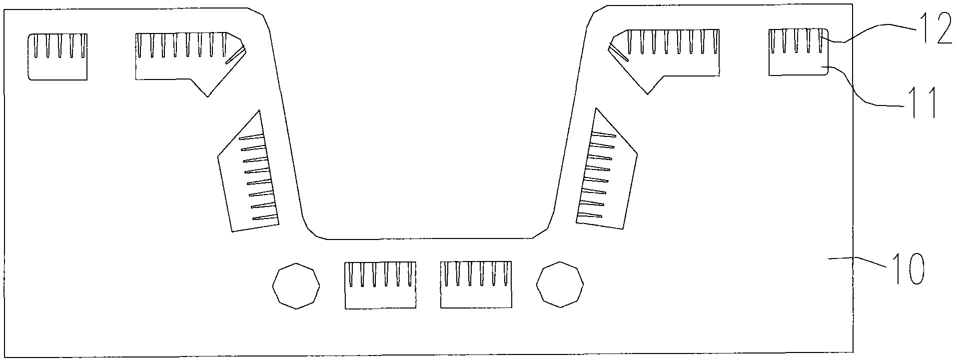
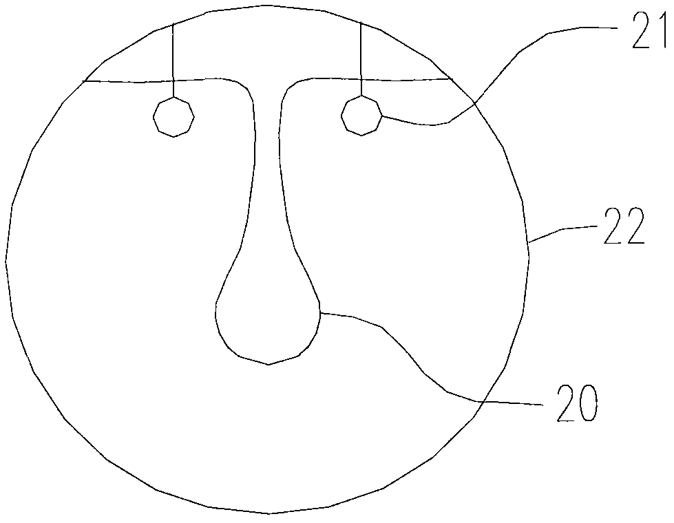
[0038] At least one cooling passage is provided in a mold, the at least one cooling passage includes a first segment and a second segment, wherein the first segment includes a first heat dissipation inner surface area, and the second segment includes a a second heat sink internal surface area; and

[0039] A heat dissipation component is used to non-uniformly adjust the first heat dissipation inner surface area and the second heat dissipation inner surface area.

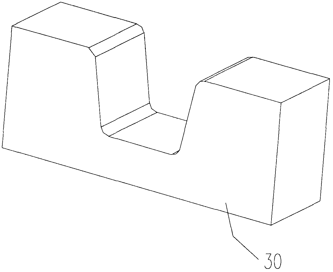
[0040] 2. The method of embodiment 1, wherein the die is a hot stamping die.

[0041] 3. The method according to any one of the above embodiments, wherein the heat dissipation component is at least one of a fin and a copper foil structure.

[0042] 4. The method according to any one of the preceding embodiments, wherein the heat dissipation component is a replaceable component.

[0043] 5. The method according to any one of the abo...


PUM


Abstract

The present invention provides a method for sectionally controlling a cooling efficiency of a mold. The method comprises steps of: (a) configuring at least a cooling passage including a first section having a first heat-dissipating inner surface area and a second section having a second heat-dissipating inner surface area in the mold; and (b) adjusting the first and the second heat-dissipating inner surface areas unequally by using a heat-dissipating element.

Description

technical field [0001] The invention relates to a mold and a method for adjusting the cooling efficiency of the mold, in particular to a hot stamping mold and a method for adjusting the cooling efficiency of the hot stamping mold in sections. Background technique [0002] In the conventional rapid mold cooling channel formation, a cooling channel is drilled with a drilling machine after the mold cavity is formed, so that cooling water can flow in the cooling channel. Drilling tools can only drill straight pipes, so the cooling water channels only have vertical and horizontal straight lines. However, the contours of the mold cavities often have curves or radians, so the distance between the cooling water channels and the mold cavity contours will vary. Lead to the problem of inconsistent cooling effect and poor temperature control effect. [0003] Hot stamping technology has the advantages of easy forming, good mechanical properties of parts after forming, and less springbac...

Claims


Application Information

Patent Timeline
Patent Type & Authority Applications(China)
IPC IPC(8): B21D37/10B21D37/16
CPCB21D37/10B21D37/16
Inventor 刘威良江子欣李明富王文彦庄志宇陈逸群
Owner METAL INDS RES & DEV CENT
Features
  • R&D
  • Intellectual Property
  • Life Sciences
  • Materials
  • Tech Scout
  • Unparalleled Data Quality
  • Higher Quality Content
  • 60% Fewer Hallucinations
Learn More