Supercharge Your Innovation With Domain-Expert AI Agents!

Bolt supporting surface sharp milling cutter and processing process for processing a bolt supporting surface of a connecting rod cap by utilizing bolt supporting surface sharp milling cutter

A bolt support and processing technology, applied in milling cutters, metal processing equipment, manufacturing tools, etc., can solve the problems of increased cutting resistance, waste, and high tool cost, and achieve the effect of improving processing quality

Inactive Publication Date: 2013-05-29
扬州苏垦银河连杆有限公司
View PDF6 Cites 1 Cited by
  • Summary
  • Abstract
  • Description
  • Claims
  • Application Information

AI Technical Summary

Problems solved by technology

In the past, it was usually processed with a vertical milling machine end mill. Due to the intermittent cutting of the tool, the tool consumption is extremely high, and the processing efficiency is low and the quality stability of the processed workpiece is not high. There is often a relatively large defective rate, resulting in great waste
[0003] At the same time, the general machining center powerful milling cutters have the same two or three blades evenly distributed to complete the cutting, but due to the influence of the width of the blade, the cutting resistance increases and cannot be formed at one time. Our parts require the root of the support surface to have an R3 angle shape , general cutting tools cannot be realized, and non-standard cutting tools or multiple cutting tools must be used for multiple processing, and the cost of cutting tools is high

Method used


Image

  • Bolt supporting surface sharp milling cutter and processing process for processing a bolt supporting surface of a connecting rod cap by utilizing bolt supporting surface sharp milling cutter
  • Bolt supporting surface sharp milling cutter and processing process for processing a bolt supporting surface of a connecting rod cap by utilizing bolt supporting surface sharp milling cutter
  • Bolt supporting surface sharp milling cutter and processing process for processing a bolt supporting surface of a connecting rod cap by utilizing bolt supporting surface sharp milling cutter

Examples


Embodiment Construction

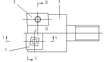
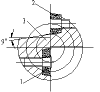
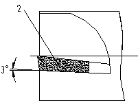
[0020] As shown in the figure, the powerful milling cutter of the present invention is composed of two different blades. The 12.7×12.7 square blade 1 and the 16.5×9.5 rhombic blade 2 are respectively arranged at 180°. 9.5 The 2 sides of the diamond-shaped blade are responsible for cutting with a diameter of φ31 on the outer edge. The functions of the two blades are different. According to the cutting principle and repeated tests, the square blade 1 undertakes the main powerful cutting task. The main cutting edge of the knife is set 0.4mm higher than the center of the knife, which is conducive to stable cutting; The 2 sides of the rhombic blade are responsible for the smoothing of the support surface and the R3 angle shape of the root of the bolt support surface. The main cutting edge of the knife is at the same height as the center of the knife, and the negative 3° makes the blade sharp when cutting the knife surface, reduces the vibration generated by cutting, and ensures the s...


PUM


Abstract

The invention relates to a bolt supporting surface sharp milling cutter and a processing process for processing a bolt supporting surface of a connecting rod cap by utilizing the bolt supporting surface sharp milling cutter. The sharp milling cutter comprises a cutter blade 1 and a cutter blade 2, wherein both of the cutter blade 1 and the cutter blade 2 are arranged on a cutter body in a dislocation manner from front to back with a certain angle; a main cutting edge of the cutter blade 1 is arranged in a manner of being higher than the cutter blade 2; the main cutting edge of the cutter blade 1 is horizontally arranged; the main cutting edge of the cutter blade 2 is provided with a dip angle being -2 degrees to -5 degrees; the cutter blade 1 is arranged on one side of the axis of the cutter body; the working radius of the cutter blade 1 corresponds to the radius of a to-be-processed workpiece; and the cutter blade 2 is also arranged on one side of the axis. When a processed material is 40Cr, the material hardness is HRc26-32 and the chamfer angle of the root of the supporting surface is R3, the selected cutter rotate speed is 1600-2000r / min and the cutting output is 40-60mm / s. According to the bolt supporting surface sharp milling cutter, a double-cutter blade structure is adopted, and the cutter blade 1 and the cutter blade 2 are skillfully matched so that the processing efficiency and the processing quality of the connecting rod cap are greatly improved.

Description

technical field [0001] The invention relates to a milling cutter for a bolt supporting surface and a processing technology for processing the bolt supporting surface of a connecting rod cover by using the milling cutter, belonging to the technical field of cutting tools. Background technique [0002] Due to the bearing capacity factor of the high-power connecting rod, a semicircular strong rib is designed around the bolt support surface of the connecting rod cover during design to protect the bolt head and improve the strength of the connecting rod cover. In the past, it was usually processed with a vertical milling machine end mill. Due to the intermittent cutting of the tool, the tool consumption is extremely high, and the processing efficiency is low and the quality stability of the processed workpiece is not high. There is often a relatively large defective rate, resulting in Great waste. [0003] At the same time, the general machining center powerful milling cutters h...

Claims


Application Information

Patent Timeline
Patent Type & Authority Applications(China)
IPC IPC(8): B23C5/02B23C3/00
Inventor 沙立新程守权
Owner 扬州苏垦银河连杆有限公司
Features
  • R&D
  • Intellectual Property
  • Life Sciences
  • Materials
  • Tech Scout
  • Unparalleled Data Quality
  • Higher Quality Content
  • 60% Fewer Hallucinations
Learn More