
Flexible material rewinding slitting system and rewinding slitting mechanism thereof

A flexible material, rewinding roller technology, applied in thin material handling, sending objects, transportation and packaging, etc., can solve the problems of affecting flexible material belts, increasing the labor intensity of operators, and occupying a large space, reducing labor intensity, The effect of improving the efficiency of rewinding and slitting

Inactive Publication Date: 2013-05-29
HENAN UNIV OF SCI & TECH
View PDF11 Cites 8 Cited by
  • Summary
  • Abstract
  • Description
  • Claims
  • Application Information

AI Technical Summary

Problems solved by technology

The rewinding and slitting device can realize the rewinding and slitting of flexible materials, but the placement of the rewinding mandrel and the transfer of the flexible material rolls require manual operations, which undoubtedly increases the labor intensity of the operators; in addition, the device uses advanced In the way of rewinding after slitting, before rewinding, in order to prevent the adjacent flexible material strips from intersecting and affecting the stretchability of the flexible material strips, there is also an arc-shaped guide roller between the slitting mechanism and the rewinding mechanism. This causes the whole device to have a complicated and huge structure, takes up a lot of space, and the production line is stretched.

Method used


Image

  • Flexible material rewinding slitting system and rewinding slitting mechanism thereof
  • Flexible material rewinding slitting system and rewinding slitting mechanism thereof

Examples


Embodiment Construction

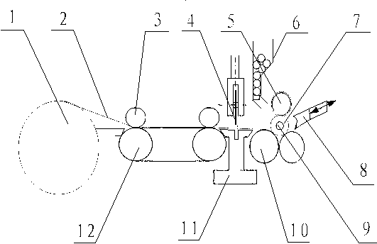
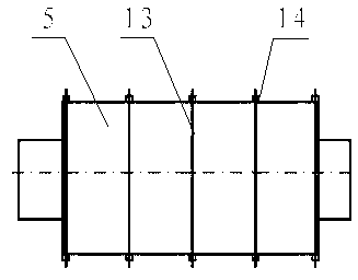
[0018] Embodiments of the flexible material rewinding and cutting system of the present invention: as Figure 1-2 As shown, including the frame (not shown in the figure), the frame is provided with a discharge mechanism, and the right side of the discharge mechanism is provided with a rewinding and cutting mechanism. The rewinding and slitting mechanism includes two rewinding rollers 10 arranged side by side and spaced apart on the frame, and a slitting and pressing roller arranged in parallel with the rewinding rollers 10 is rotatably mounted directly above the middle of the two rewinding rollers 10 5. In this way, the slitting and pressing roller 5 and the two rewinding rollers 10 form a triangular distribution state, and the triangular area between the three is the rewinding area for the rewinding mandrel 9 to enter side by side. On the outer peripheral surface of the slitting and pressing roller 5 Annular slitting knives 13 extending circumferentially along the slitting an...


PUM


Abstract

The invention discloses a flexible material rewinding slitting system and a rewinding slitting mechanism thereof. The mechanism comprises a machine frame and two rewinding rollers which are assembled on the machine frame in a rotation mode. A slitting pressing roller is assembled above the middle portions of the two rewinding rollers in the rotation mode. The slitting pressing roller moves along the radial direction of a rewinding core shaft so that the rewinding core shaft is pressed between the slitting pressing roller and the two rewinding rollers. At least one rewinding roller is a driving roller for achieving rotation of the rewinding core shaft. Annular slitting cutters are distributed on the outer periphery of the slitting pressing roller in the radial direction in a spaced mode and extend along the circumferential direction of the slitting pressing roller, and flexible material rolls are slit by the annular slitting cutters. A working mode of slitting while rewinding is adopted by the rewinding slitting mechanism, compared with the prior art, the inter-related phenomenon of the flexible materials is avoided, the positions of the slitting pressing roller, the rewinding core shaft and the rewinding rollers are relatively closer, occupied space of the whole rewinding slitting mechanism is compressed, the length of the rewinding slitting system of the rewinding slitting mechanism is compressed, and the flexible material rewinding slitting system and the rewinding slitting mechanism of the flexible material rewinding slitting system are simple and compact in structure.

Description

technical field [0001] The invention relates to a flexible material rewinding and cutting system and its rewinding and cutting mechanism. Background technique [0002] After the flexible materials are processed on the production line, special equipment is required for rewinding and cutting. Chinese patent CN202346479U discloses a rewinding and cutting device, which is mainly composed of a feeding mechanism, a cutting mechanism and a rewinding mechanism. The material mechanism includes a discharge roller, the slitting mechanism is mainly composed of two external cutting knives, and the rewinding mechanism includes a rewinding mandrel and two rewinding rollers arranged side by side under the rewinding mandrel. One of the rolls is a driving roll. During application, the flexible material is discharged by the discharge roller, and then passes through the gap between the two slitting knives. The slitting knife cuts the flexible material into flexible material strips, and each fl...

Claims


Application Information

Patent Timeline
IPC IPC(8): B65H35/02
Inventor 杨建玺杨丙乾张发玉
Owner HENAN UNIV OF SCI & TECH
Learn More