Dysmorphism rod curved line drafting device

A drafting device and special-shaped rod technology, which is applied in the field of spinning technology, can solve the problems of moving forward, concentrating, and stabilizing the speed change point affecting fibers, and small fiber control force, etc., to achieve reduction Effect of planktonic zone length, enhanced control, yarn evenness and hairiness improvement

Inactive Publication Date: 2013-05-29
程心一
View PDF5 Cites 6 Cited by
  • Summary
  • Abstract
  • Description
  • Claims
  • Application Information

AI Technical Summary

Problems solved by technology

The outlet of the elastic nip of the double rubber ring is between the front roller and the front nip composed of the front rubber roller. The fiber is not constrained, which is usually called the floating area. The larger the floating area, the fiber changes from slow fiber to fast fiber. The more backward, the less concentrated, the worse the evenness of the yarn; the height of the outlet of the elastic jaw of the double apron used now is more than 10mm, limited by the space given by the front roller and the front rubber roller, it cannot move forward Stretching, resulting in the unconstrained floating area of ​​the fiber in the drafting area in front of the spinning frame is more than 10 mm, which affects the further forward movement of the fiber speed change point; in addition, because the middle part of the upper and lower rubber rings is too soft, the main drafting area The control force of the middle and rear fibers is very small, which also affects the forward movement, concentration, and stability of the fiber shift point

Method used


Image

  • Dysmorphism rod curved line drafting device
  • Dysmorphism rod curved line drafting device
  • Dysmorphism rod curved line drafting device

Examples


Embodiment Construction

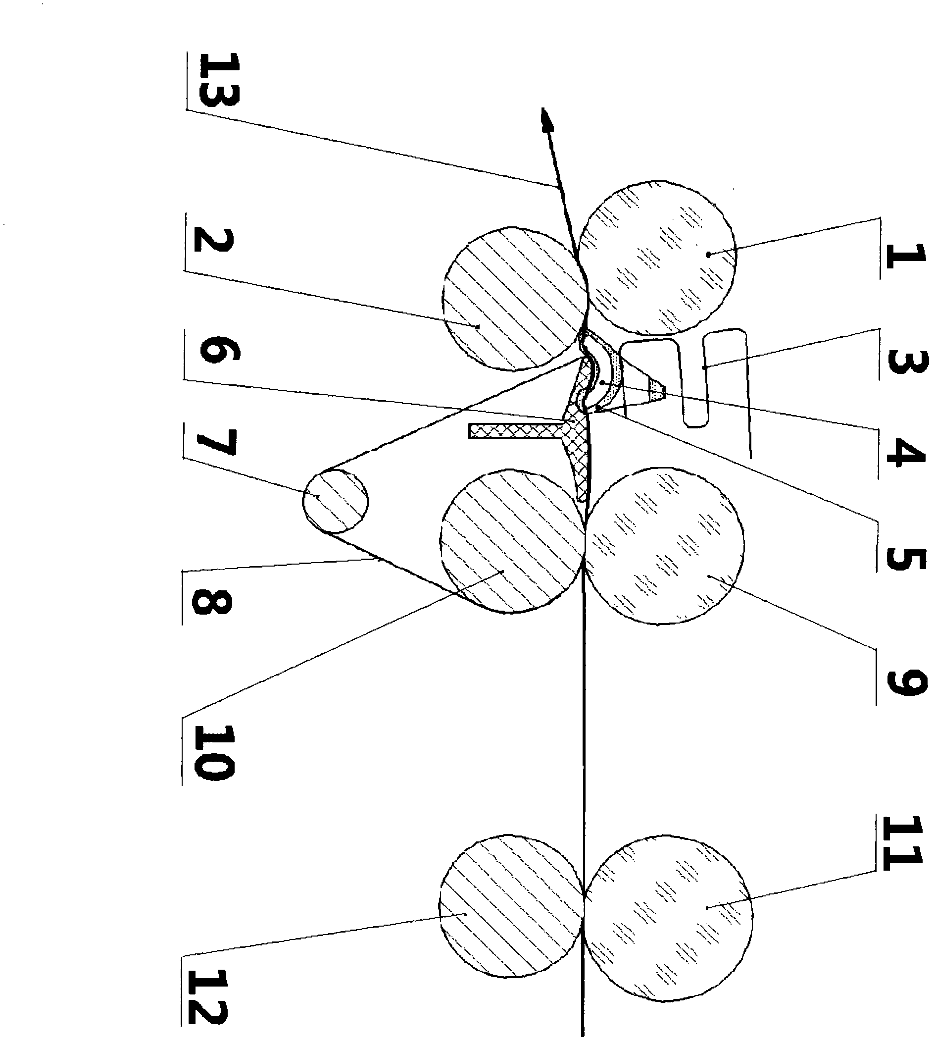
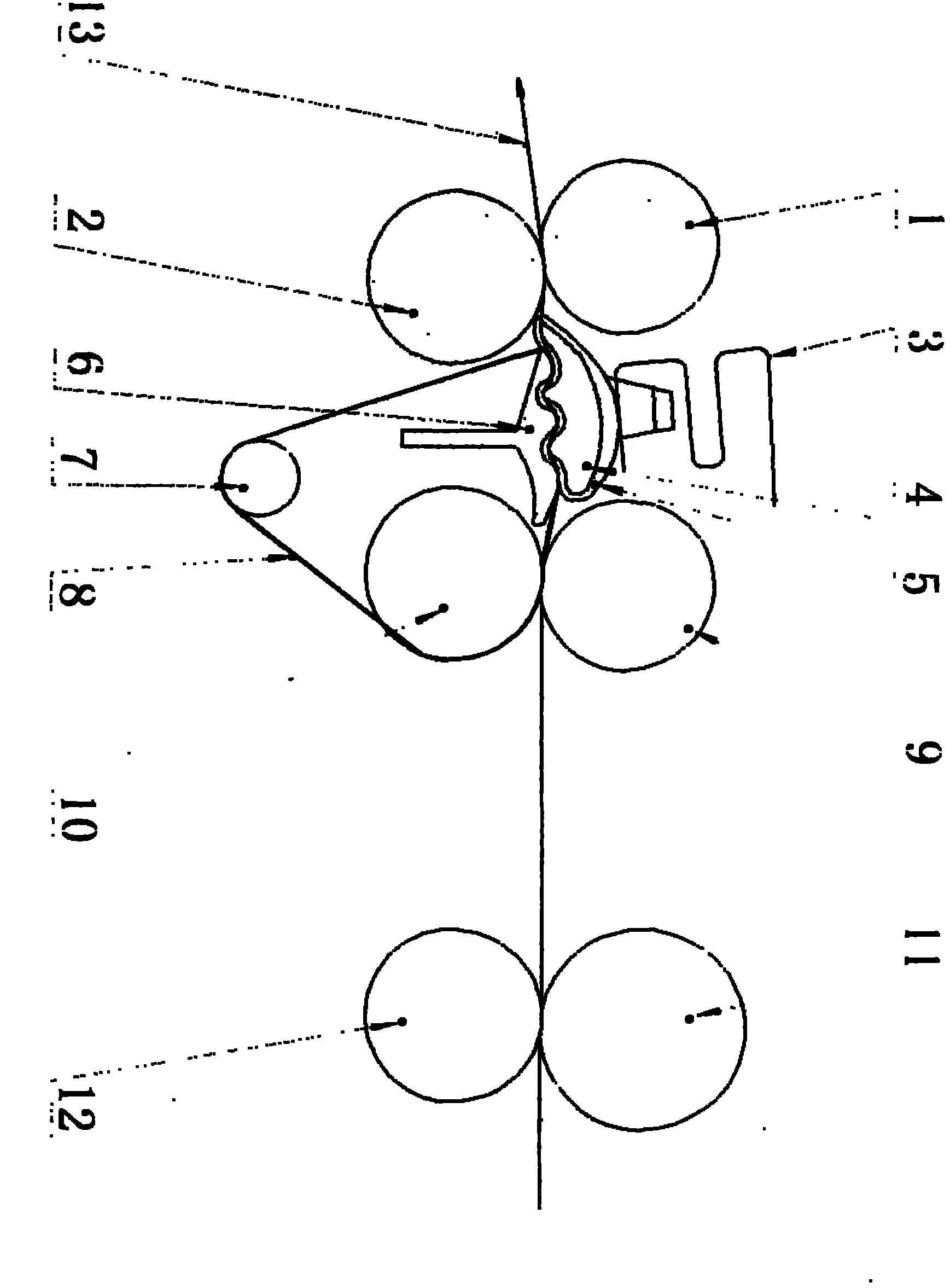
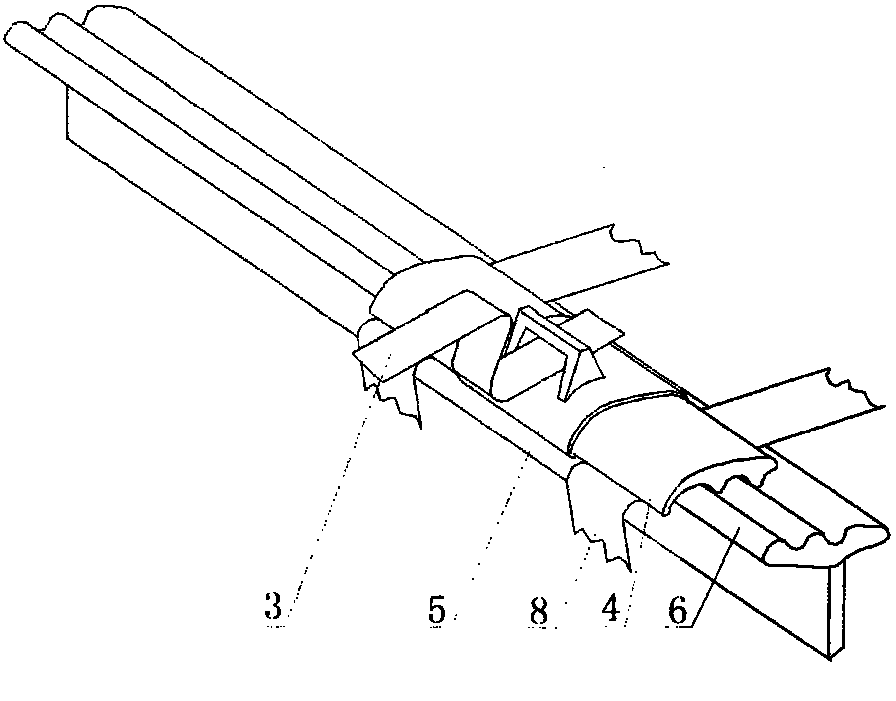
[0013] As shown in the figure, the middle lower ring (8) is sleeved on the concave-convex lower pin (6), the middle roller (10) and the tension device (7). The middle positioning body (5) is in the middle of the special-shaped rod (4), and the middle positioning body ( 5) Under the action of the compression spring (3), it is pressed tightly on the concave-convex lower pin (6), and the intermediate positioning body (5) separates the special-shaped rod (4) from the concave-convex lower pin (6) to form a fiber bundle conveying The curved drafting channel allows the fiber bundle (13) and the lower circle (8) to pass. The fiber bundle (13) passes through the lower surface of the special-shaped rod (4) under the support of the lower ring (8), the upper end of the compression spring (3) is connected with the cradle, the lower end is connected with the intermediate positioning body (5), and the compression spring (3) The special-shaped rod (4) can be easily lifted or pressed on the con...


PUM


Abstract

The invention provides a dysmorphism rod curved line drafting device and is suitable for the field of spins. The dysmorphism rod curved line drafting device comprises a front clamping opening composed by a front roller and a front rubber roller, a middle clamping opening composed by a middle roller and a middle rubber roller, a back clamping opening composed by a back roller and a back rubber roller, a dysmorphism rod, a middle positioning body, a concave and a protruding surface lower pin, a pressure spring, a lower ring and a lower ring tension device. The dysmorphism rod, a middle positioning body, a concave surface and a protruding surface lower pin, a pressure spring, a lower ring and a lower ring tension device are arranged between the front clamping opening and the middle clamping opening. The dysmorphism rod curved line drafting device is characterized in that a convex-concave is arranged on the lower surface of the dysmorphism rod perpendicular to the axis line direction and the convex-concave is arranged in a wave shape. A convex-concave is arranged on the surface of the concave and convex lower pin perpendicular to the axis line direction and the convex-concave is arranged in a wave shape. A curved line drafting passage is formed by the coordination of the protruding and concave part of the dysmorphism rod and the concave and the protruding of the concave and protruding lower pin. Restraining force of a fibre bundle in the middle and the back portion of a main drafting area is strengthened. The length of a floating zone in a front drafting area of a spinning machine is reduced. The dysmorphism rod curved line drafting device is beneficial to the forward displacement, focus and stability of a speed changing of the fibre.

Description

Technical field [0001] The invention relates to a spinning technology. Background technique [0002] The use of double apron elastic nip drafting in the main drafting zone of the ring spinning frame has a history of nearly one hundred years. The outlet of the double rubber ring elastic nip is between the front nip formed by the front roller and the front rubber roller. The fiber is not constrained. It is usually called the floating area. The larger the floating area, the shift point of the fiber from slow fiber to fast fiber. The more backward and less concentrated, the worse the yarn evenness; the height of the elastic jaw exit of the double rubber ring used now is more than 10 mm, and it cannot be moved forward due to the limitation of the space given by the front roller and the front rubber roller Stretching causes the unconstrained floating zone of the fiber in the drafting zone of the spinning frame to be above 10 mm, which affects the further advancement of the fiber shift...

Claims


Application Information

Patent Timeline
Patent Type & Authority Applications(China)
IPC IPC(8): D01H5/26
Inventor 程心一
Owner 程心一
Why Eureka
Try Eureka