Power supply aging system

A power supply aging and power supply technology, applied in power supply testing, irreversible DC power input conversion to AC power output, etc., can solve problems such as high cost and waste of electric energy

Inactive Publication Date: 2013-05-29
XIAN BOYU GREEN ENERGY
View PDF0 Cites 3 Cited by
  • Summary
  • Abstract
  • Description
  • Claims
  • Application Information

AI Technical Summary

Problems solved by technology

[0003] In order to overcome the deficiencies of the above-mentioned prior art, the purpose of the present invention is to provide a power

Method used


Image

  • Power supply aging system

Examples


Embodiment Construction

[0011] The present invention will be described in further detail below in conjunction with the accompanying drawings and embodiments.

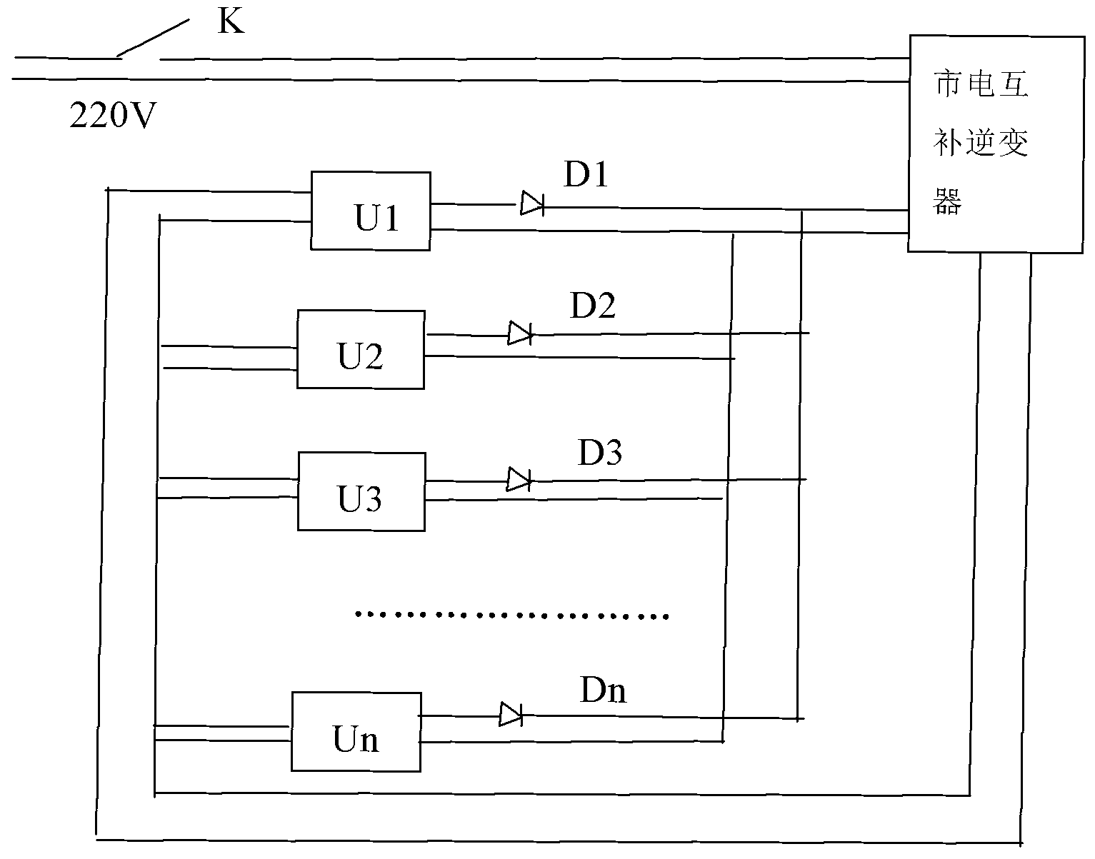
[0012] As shown in the drawings, the present invention is a power aging system, a power aging system, the mains power is input to the mains complementary inverter through the static switch K, and the output of the mains complementary inverter is connected to the aged power U The input end of the aging power supply U is connected to the mains complementary inverter through the diode D. The number of aging power sources U is multiple (U1-Un), which are arranged in parallel, and the corresponding number of diodes D is also multiple (D1-Dn).

[0013] The static switch is responsible for the switch control of the whole system; the diode has unidirectional conductivity, which can prevent the output current of each aging power supply from causing reverse series damage to the power supply, and protect the electronic components in the power aging syste...


PUM


Abstract

The invention relates to a power supply aging system. A mains supply is inputted to a mains supply complementary inverter through a static switch K, output of the mains supply complementary inverter is connected to input ends of a plurality of aged power supplies U, output ends of the aged power supplies U are connected to the mains supply complementary inverter through a plurality of diodes D, the aged power supplies U are connected in parallel, the static switch K is controlled by a logic circuit, and the mains supply complementary inverter A is used for collecting current, converting direct current into alternating current and modulating phases, electric energy in the circuit is recycled, and proper electric energy is absorbed from the mains supply to supply power. The power supply aging system solves the problem of high cost due to waste of a large amount of electric energy of a traditional power supply aging device.

Description

technical field [0001] The invention relates to a power aging device, in particular to a power aging system. Background technique [0002] The aging test of electronic products is a necessary means to control the quality of electronic products and eliminate the hidden dangers of early failure of electronic products. As an electronic product or an integral part of an electronic product, the stability of the power supply directly affects the stability of the electronic product, so a strict aging test is required before the power supply leaves the factory. At present, the general power aging system uses cement resistors or other purely resistive modules as its power load for aging, so that electric energy is wasted through the power load during the power aging process, which is extremely inconsistent with the policy requirements of energy conservation and environmental protection. Moreover, as the model and specification of the power supply change, it is necessary to re-select...

Claims


Application Information

Patent Timeline
IPC IPC(8): H02M7/42G01R31/40
Inventor 张晓哲王丰飞
Owner XIAN BOYU GREEN ENERGY
Why Eureka
Try Eureka