Magnetic separation device for dry magnetic separator
A magnetic separation device, dry magnetic separation technology, applied in the direction of magnetic separation, solid separation, chemical instruments and methods, etc., can solve the problems of multiple packages and inclusions, unsatisfactory mineral grades, and unsatisfactory recovered mineral grades, etc., to improve The effect of recovery and grade
- Summary
- Abstract
- Description
- Claims
- Application Information
AI Technical Summary
Problems solved by technology
Method used
Image

Examples
Embodiment 1
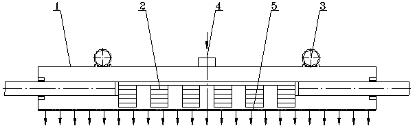
[0028] like figure 1 The magnetic system of a vibrating magnetic separator shown mainly includes a non-magnetic air chamber 1 (which can be disc-type, box-type, drum-type or other shapes), magnetic system 2 (permanent magnet or electromagnet, etc.), A vibrating device 3 to vibrate the air chamber 1; the air chamber 1 is closed and an air inlet 4 is set at a suitable position, and the working surface is a ventilating plate 5 with air holes to form an air passage; On the driving part; the magnetic system 2 is fixed in the air cavity 1 through an external support to form a relative translational movement with the air cavity 1. In this embodiment, the magnetic system 2 is fixed, the air cavity 1 translates along the axis, and the movement direction of the air cavity 1 is in line with the The direction of the magnetic force of the magnetic system 2 is vertical and the speed is controllable. The direction of the magnetic force of the magnetic system 2 is opposite to the direction of...
Embodiment 2
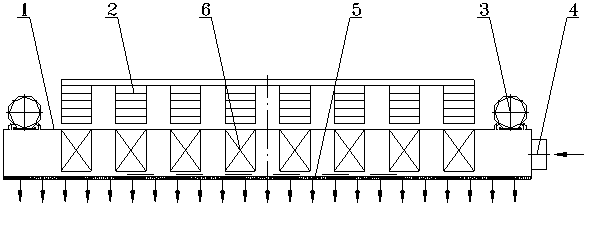
[0031] like image 3 As shown, this embodiment is basically the same as Embodiment 1, the difference is that the magnetic system 2 is fixed on the outside of the air cavity 1 opposite to the air-permeable plate 5 through external support, and the magnetic medium 6 is fixed on the air cavity corresponding to the magnetic system 2 1, the rest with figure 1 same. In this optimal solution, the magnetic system 2 is installed outside the air cavity and the magnetic force range is extended through the magnetic medium 6, which not only ensures the sorting effect, but also avoids the sealing between the external support of the magnetic system 2 and the air cavity 1 in solution 1. question.
Embodiment 3
[0033] Figure 4 and Figure 5It is another embodiment of this patent. This embodiment is basically the same as Embodiment 1. The difference is that in this embodiment, the air cavity 1 is a hollow cylinder that rotates around an axis, and the speed is controllable. The cylinder body is equipped with The air-permeable plate 5 with air holes is made, the magnetic system 2 is fixed in the air cavity 1, and forms a relative rotational motion with the rotating air cavity 1, and the air inlet 4 is set on the hollow shaft connected to the air cavity 1 and connected to the pressure gas , Vibration device 3 is located on the shaft. In this embodiment, the material to be selected is conveyed from the bottom of the air cavity 1, and the magnetic material and its packaged inclusions are adsorbed to the working surface of the air-permeable plate 5 under the action of the magnetic system 2, and the non-magnetic material is sent to the tailings mouth. At this time, the materials adsorbed ...
PUM
| Property | Measurement | Unit |
|---|---|---|
| Air resistance | aaaaa | aaaaa |
| Roughness | aaaaa | aaaaa |
Abstract
Description
Claims
Application Information
 - Generate Ideas
- Intellectual Property
- Life Sciences
- Materials
- Tech Scout
- Unparalleled Data Quality
- Higher Quality Content
- 60% Fewer Hallucinations
Browse by: Latest US Patents, China's latest patents, Technical Efficacy Thesaurus, Application Domain, Technology Topic, Popular Technical Reports.
© 2025 PatSnap. All rights reserved.Legal|Privacy policy|Modern Slavery Act Transparency Statement|Sitemap|About US| Contact US: help@patsnap.com