Bowl scaffold steel tube derusting machine

A scaffolding and derusting machine technology, applied in the field of scaffolding steel pipe derusting machine and bowl buckle type scaffolding steel pipe derusting machine, can solve the problems of cleaning machine damage, collision, inability to derust the whole steel pipe, etc. The effect of reducing vibration and easy operation

Active Publication Date: 2013-06-05
FANGYUAN CONSTR GRP REAL ESTATE DEVT CO LTD
View PDF7 Cites 4 Cited by
  • Summary
  • Abstract
  • Description
  • Claims
  • Application Information

AI Technical Summary

Problems solved by technology

This patent removes the rust spots by rubbing the steel wire wheel with the surface of the steel pipe, and the cleaning function can complete the rust removal process well when operating ordinary scaffolding; There is a bowl buckle joint on the top, which cannot quickly and effectively derust the entire steel pipe, and the cleaning machine will collide with the bowl buckle when the wire wheel is operating, causing damage to the cleaning machine

Method used


Image

  • Bowl scaffold steel tube derusting machine
  • Bowl scaffold steel tube derusting machine
  • Bowl scaffold steel tube derusting machine

Examples


Embodiment 1

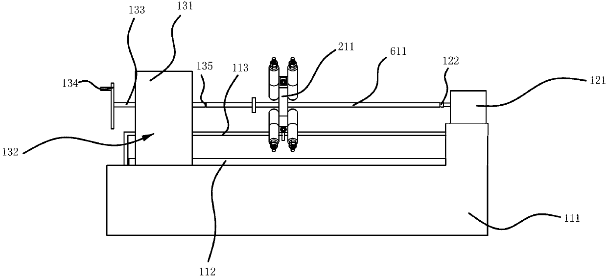
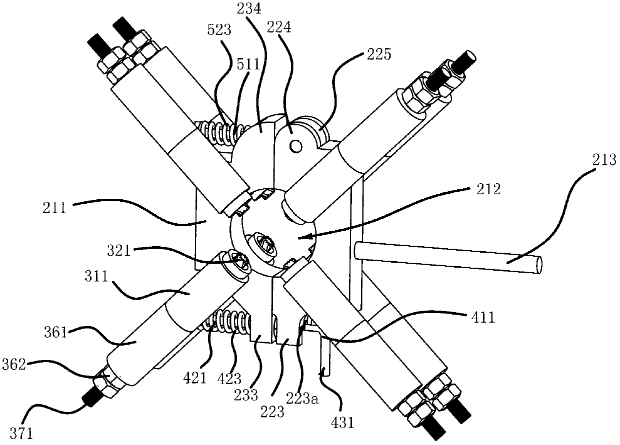
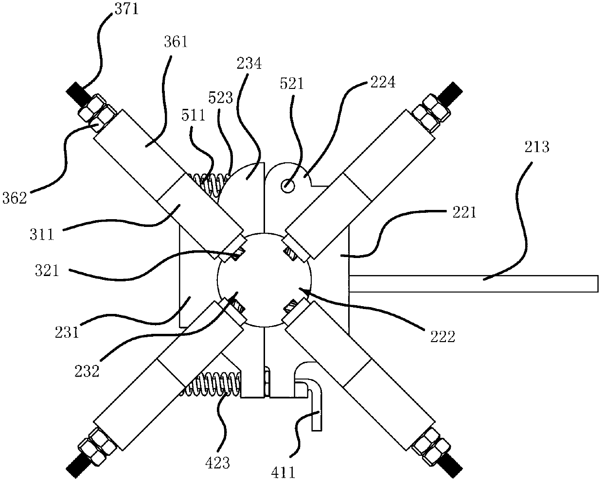
[0028] Such as Figure 1 to Figure 5 As shown, a bowl buckle type scaffolding steel pipe derusting machine includes a frame 111 and a derusting ring 211, and one end of the frame 111 is fixed with a deceleration motor 121, and the deceleration motor 121 in the present embodiment one is available on the market For example, the YCJ series gear reducer produced by Zibo Fumate Transmission Equipment Co., Ltd., the other end of the frame 111 is provided with a fixed seat 131, and the fixed seat 131 can move along the frame 111 to position the steel pipe 611 on the geared motor 121 and fix it Between the seats 131, the side of the frame 111 is axially fixed with a retaining rod 113, such as figure 2 As shown, the rust removal ring 211 has a through hole 212 for the steel pipe 611 to pass through. Fixed sleeve 311, the central axis of fixed sleeve 311 is parallel to the side of derusting ring 211 and intersects with the central axis of through hole 212, the inner end of fixed sleev...

Embodiment 2

[0035] The structure and principle of this embodiment are basically the same as that of Embodiment 1, the difference is that the adjustment assembly includes gasket 1 fixed on one end of the brush head, a buffer spring and a cover plate, and the buffer spring is sleeved on the brush head to buffer One end of the spring abuts against the gasket one, one end of the cover plate is provided with a groove, the groove wall of the groove is provided with an internal thread, the cover plate is threadedly connected with the fixing sleeve, and the gasket one abuts against the groove bottom surface of the groove. By adjusting the length of the threaded connection between the cover plate and the fixed sleeve, the length of the brush head protruding from the fixed sleeve is adjusted.

Embodiment 3

[0037] The structure and principle of this embodiment are basically the same as that of Embodiment 1, except that the locking structure includes a locking part 1 protruding from the other end of the rotating plate, a locking part 2 protruding from the other end of the fixed plate and screws , locking part 1 and locking part 2 can lean against each other, screw hole 1 is set on locking part 1, screw hole 2 is set on locking part 2, internal thread is set on the hole wall of screw hole 2, screw hole 1 and screw hole The two phases are connected, and the screw passes through the first screw hole and is threadedly connected with the second screw hole.


PUM


Abstract

The invention provides a bowl scaffold steel tube derusting machine and belongs to the technical field of machinery. The bowl scaffold steel tube derusting machine solves the technical problems that rust cleaning of the whole bowl scaffold steel tube is unavailable for an existing bowl scaffold steel tube derusting machine and the like. The bowl scaffold steel tube derusting machine comprises a machine frame and a derusting ring. A speed reduction motor is fixed at one end of the machine frame. A fixing seat is arranged at the other end of the machine frame. A blocking rod is arranged on the lateral portion of the machine frame along the axial direction. A through hole is formed in the derusting ring and the steel tube passes through the through hole. A limiting rod which is capable of butting against the blocking rod is arranged on the periphery of the derusting ring. A plurality of fixing sleeves are fixed on the lateral sides of the derusting ring. The central axes of the fixing sleeves are parallel to the lateral sides of the derusting ring and intersect with the central axis of the through hole. Brush heads are arranged on the inner ends of the fixing sleeves. An adjusting component is arranged between each fixing sleeve and each corresponding brush head, wherein the adjusting component is capable of enabling the brush head to move along the direction of the axis of the fixing sleeve. The bowl scaffold steel tube derusting machine has the advantages of being capable of effectively cleaning rust on the bowl scaffold steel tube.

Description

technical field [0001] The invention belongs to the technical field of machinery, and relates to a rust remover for scaffold steel pipes, in particular to a bowl button type rust remover for scaffold steel pipes. Background technique [0002] Scaffolding refers to various supports erected on the construction site for workers to operate and solve vertical and horizontal transportation. At present, the safety scaffolds for production are all constructed of steel pipes. Scaffolding is made of iron materials. Due to the harsh environment of the construction site, the surface of the scaffolding will be covered with rust spots after one use. Before the next use, the scaffolding needs to be maintained and painted, so the rust spots on the surface of the scaffolding need to be removed. [0003] At present, the process of derusting is completed by machine, such as the scaffolding steel pipe cleaning machine [CN201632893U] disclosed in Chinese patent literature, which is composed of s...

Claims


Application Information

Patent Timeline
Patent Type & Authority Applications(China)
IPC IPC(8): B24B27/033
Inventor 陈方春金崇正缪文忠林华桥杨国兵
Owner FANGYUAN CONSTR GRP REAL ESTATE DEVT CO LTD
Why Eureka
Try Eureka