Vehicle instrument apparatus

A vehicle and instrument technology, applied to measuring devices, devices using electric/magnetic methods, instruments, etc., can solve the problems of reduced speed detection accuracy, increased replacement man-hours, and increased number of parts, and achieve the goal of suppressing speed detection errors Effect

Active Publication Date: 2013-06-05
HONDA MOTOR CO LTD
View PDF3 Cites 5 Cited by
  • Summary
  • Abstract
  • Description
  • Claims
  • Application Information

AI Technical Summary

Problems solved by technology

[0004] The vehicle speed detection device provided in the conventional eddy current speedometer described in Patent Document 1 is formed by fixing the board on which the Hall element is mounted to the frame member with bolts. The output voltage of the hall element due to the change of the magnetic field changes, so in the device that detects the vehicle speed through the change of the magnetic field, the speed value to be detected deviates, resulting in a decrease in the speed detection accuracy
[0005] Therefore, as a general measure to prevent bolts from falling off or loosening, it is considered to install an iron piece on the frame member side of the meter device, and to tighten the iron piece and then bend it along the side surface of the bolt head. In addition to the bolts, iron sheets are required, so the number of parts increases, and the shape of the head of the bolts is limited to quadrilateral, hexagonal, etc. In addition, new iron sheets need to be replaced every time the bolts are installed and removed, so there is a problem. Technical issues that require increased man-hours for replacement and poor workability

Method used


Image

  • Vehicle instrument apparatus
  • Vehicle instrument apparatus
  • Vehicle instrument apparatus

Examples


Embodiment Construction

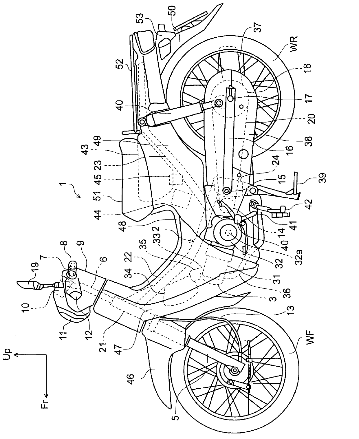
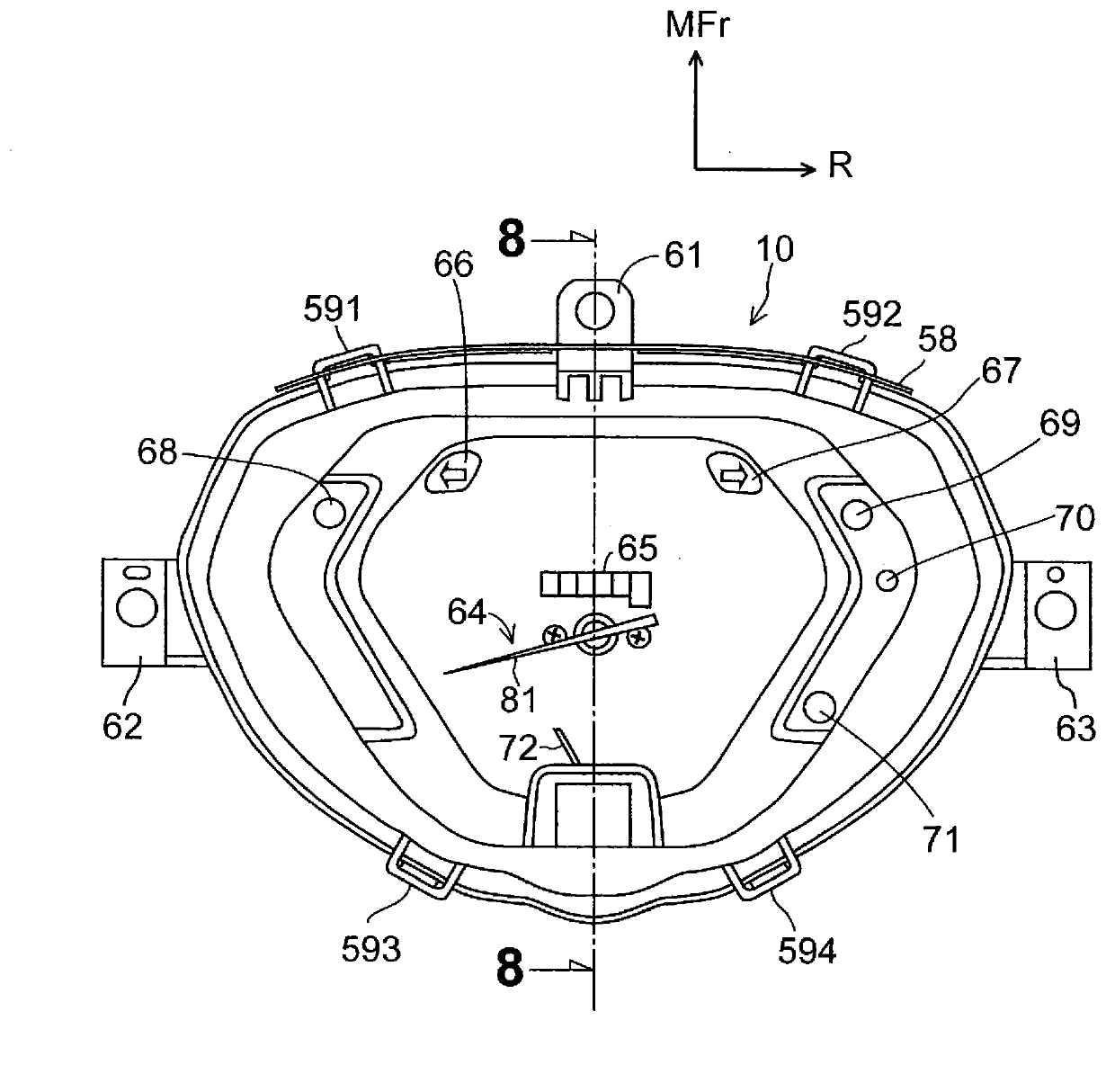
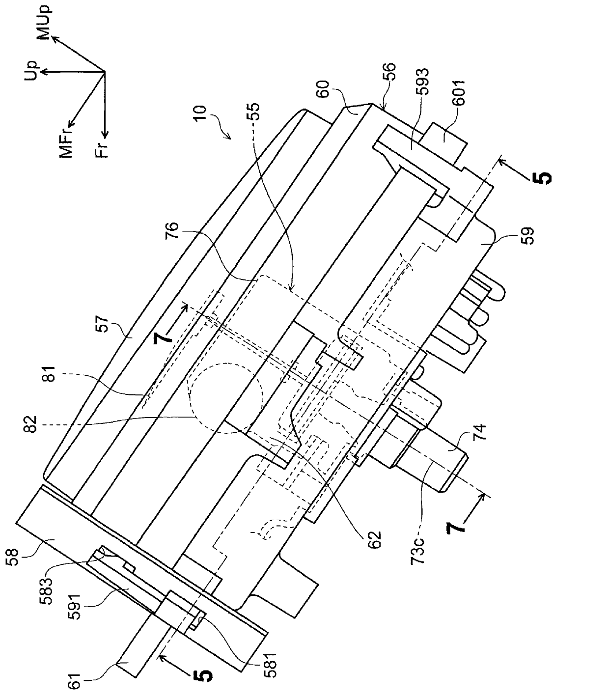
[0039] Hereinafter, one embodiment of the present invention will be described with reference to the drawings. referred to below figure 1 , image 3 In the diagram, the front of the motorcycle 1 is indicated by the reference symbol Fr, the left and right sides of the motorcycle 1 are indicated by the reference symbols L and R, respectively, and the upper side of the motorcycle 1 is indicated by the reference symbol Up. in addition, figure 2 , Figure 4 ~ Figure 12 It is a diagram showing the meter device 10 tilted backward with respect to the motorcycle 1 . exist figure 2 , Figure 4 ~ Figure 12 In the figure, the axial direction upward of the pointer shaft 100 of the speedometer of the meter device 10 is indicated by MUp, and the front in the direction perpendicular to the direction MUp of the meter device 10 is indicated by MFr.

[0040] figure 1 It is a left side view of a motorcycle equipped with a meter device including a vehicle speed detection device according t...


PUM


Abstract

The invention provides a vehicle instrument apparatus provided with an anti-falling configuration for fixing a sensor support block provided with a speed sensor on a fasten part (a screw) of a shield part of the instrument apparatus. The apparatus is provided with a rotor (85) provided with magnet (98) and synchronously rotating with rotation of a wheel (WF) and the speed sensor (86) configured in a magnetic path of the magnet (98). Rotation of the rotor (85) is detected based on magnetic field change of the magnetic path. The speed sensor (86) is mounted on a sensor substrate (87). The sensor substrate (87) is fixed on a rotor support rack (76) by fixed screws (92,93). A shielding part (59) covers around the rotor support rack (76) and accommodates the rotor (85), the speed sensor (86), sensor substrate (87) and a sensor support block (88). Libs (83,84) of a wall (130) for preventing the fixed screws (92,93) from falling off in a state of accommodating the sensor substrate (87) and the sensor support block (88) are disposed on a shield part (59).

Description

technical field [0001] The present invention relates to a meter device for a vehicle, and more particularly to a meter device for a vehicle having a mounting structure for mounting a sensor substrate supporting a speed sensor to a frame member of the meter device. value above. Background technique [0002] There is known an eddy current type speedometer which has: a magnet provided on a rotating shaft through which the rotation of a wheel is transmitted via a flexible cable; The pointer combined with the sensor plate coupled with rotational displacement due to the eddy current generated by the rotation of the magnet performs speed display (for example, the speedometer described in Patent Document 1). This speedometer has a speed detection device that detects a change in the magnetic field caused by the rotation of the magnet with a magnetoelectric conversion element (Hall element) and activates an alarm when the speed of the vehicle exceeds a predetermined value. [0003] ...

Claims


Application Information

Patent Timeline
Patent Type & Authority Applications(China)
IPC IPC(8): B62J99/00G01P3/42G01P1/02
Inventor 濑之口裕太
Owner HONDA MOTOR CO LTD
Why Eureka
Try Eureka