A water-suspended weightless multifunctional power generation device

A power generation device and weightless technology, which is applied in wind power generation, hydropower generation, renewable energy generation, etc., can solve the problems of large water level drop, metal fatigue, small stress area of ​​generator water leaves, etc., and achieve simple structure Effect

Active Publication Date: 2015-09-09
袁荏祥
View PDF7 Cites 0 Cited by
  • Summary
  • Abstract
  • Description
  • Claims
  • Application Information

AI Technical Summary

Problems solved by technology

[0002] The utilization of renewable energy has become a new direction of energy utilization. For a kind of renewable energy, wind power generators are also the main direction of renewable energy development. There are some problems in traditional wind power generators, such as: the generator blades have a small wind area , The conversion rate of energy utilization is low, and the fan blades should not be too large. In case of strong typhoons and bad weather, brakes are required to stop the operation. When the fan blades rotate, they need to consume a part of energy to eliminate their own weight. There is metal fatigue, and the windward angle needs to be adjusted. The differential is small wind can't generate electricity
[0003] The utilization of renewable energy has become a new direction of energy utilization. For a kind of renewable energy, hydropower generators are also the main direction of renewable energy development. There are some problems in traditional hydropower generators, such as: the force on the water leaves of the generator The area is small, the conversion rate of energy utilization is low, dams need to be built, the investment is huge, the water level difference must be large, the rotating water blades cannot be too large, and the rotating water blades need to consume part of the energy to eliminate their own weight when rotating, and there is metal fatigue phenomenon. , the water flow is too small to generate electricity

Method used


Image

  • A water-suspended weightless multifunctional power generation device
  • A water-suspended weightless multifunctional power generation device
  • A water-suspended weightless multifunctional power generation device

Examples


Embodiment Construction

[0021] In order to better understand the contents of the present invention and understand the reasons for producing such beneficial effects, we provide specific implementations in conjunction with the accompanying drawings to further illustrate the present invention.

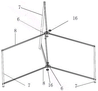
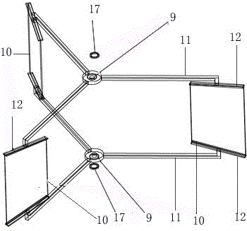
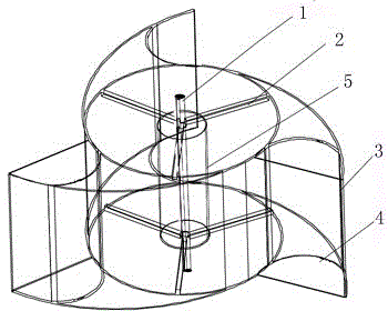
[0022] refer to Figure 1 to Figure 7 , a water-suspended weightless multifunctional power generation device, including a fixing seat (such as figure 1 shown), auxiliary vane mechanism (such as figure 2 shown), rotating body (such as image 3 with Figure 5 shown), and the energy conversion device that cooperates with the rotating body, and the buoyancy reducer 5 designed integrally with the rotating body, the rotating body includes a fixed central shaft 1, and a fixed bracket 2 arranged on the fixed central shaft 1 , and the energy collection sheet 3 connected on the fixed support 2, and the energy collection cover 4 integrated with the energy collection sheet 3, the energy collection sheet 3 adopts a semi-...


PUM


Abstract

The invention discloses an aqueous suspension antigravity multifunction power generation device which comprises a fixed seat, an auxiliary vane mechanism, a rotating body, an energy conversion device which is matched with the rotating body and a buoyancy weight saver which is designed integrally with the rotating body. The aqueous suspension antigravity multifunction power generation device has the advantages that an energy conversion rate is close to 100%. The structure is simple, the aqueous suspension antigravity multifunction power generation device can be big or small, a frame structure is utilized, and the aqueous suspension antigravity multifunction power generation device is small in wind pressure, can resist a super typhoon, and can be operated the whole day in bad weather. A metal fatigue phenomenon is not produced. A universal structure is utilized, and an attack angle does not need to be regulated. The buoyancy weight saver is used for offsetting weight of the rotating body, and thus the rotating body can be rotated in weak fluids. Resources are rich, and the power generation device can be used in places with water flowing and wind flowing. Construction cost is low, and the power generation device is economical, practical and environment-friendly.

Description

technical field [0001] The invention relates to a power generation device utilizing wind energy or water energy to generate electricity, in particular to a weightless multifunctional power generation device suspended in water. Background technique [0002] The utilization of renewable energy has become a new direction of energy utilization. For a kind of renewable energy, wind power generators are also the main direction of renewable energy development. There are some problems in traditional wind power generators, such as: the generator blades have a small wind area , the conversion rate of energy utilization is low, and the fan blades should not be too large. In case of strong typhoons and bad weather, brakes are required to stop the operation. When the fan blades rotate, they need to consume a part of energy to eliminate their own weight. There is metal fatigue, and the windward angle needs to be adjusted. The differential is small Wind cannot generate electricity. [000...

Claims


Application Information

Patent Timeline
Patent Type & Authority Patents(China)
IPC IPC(8): F03B3/12F03D11/00
CPCY02E10/722Y02E10/223Y02E10/20Y02P70/50
Inventor 袁荏祥
Owner 袁荏祥
Why Eureka
Try Eureka