Spiral steel, application product of same, and method for manufacturing spiral steel

A manufacturing method, the technology of spiral steel, applied in the field of spiral steel, can solve the problems of flat steel difficult to process, longitudinal bending, deformation, etc., and achieve the effect of shortening the pitch and improving the mechanical strength

Inactive Publication Date: 2013-06-05
后藤常郎
View PDF20 Cites 4 Cited by
  • Summary
  • Abstract
  • Description
  • Claims
  • Application Information

AI Technical Summary

Problems solved by technology

However, for the compressive force from the long-axis direction of the twisted flat steel, by figure 1 Bending load applied in the vertical direction, for example, easily deforms at the position indicated by the arrow, and cannot obtain sufficient mechanical strength
[0007] Therefore, it is difficult to use the twisted flat steel itself for the pillars of the structure, and if it is desired to increase the mechanical strength, it requires corresponding secondary processing, etc., which will have a negative impact on the difficulty and efficiency of processing.
In addition, twisted flat steel may be difficult to process in the direction of shortening the pitch of the flat steel, or longitudinal warp may occur.

Method used


Image

  • Spiral steel, application product of same, and method for manufacturing spiral steel
  • Spiral steel, application product of same, and method for manufacturing spiral steel
  • Spiral steel, application product of same, and method for manufacturing spiral steel

Examples


Embodiment Construction

[0065] Hereinafter, the spiral steel of the present invention, its application products, and the manufacturing method of the spiral steel will be described in detail.

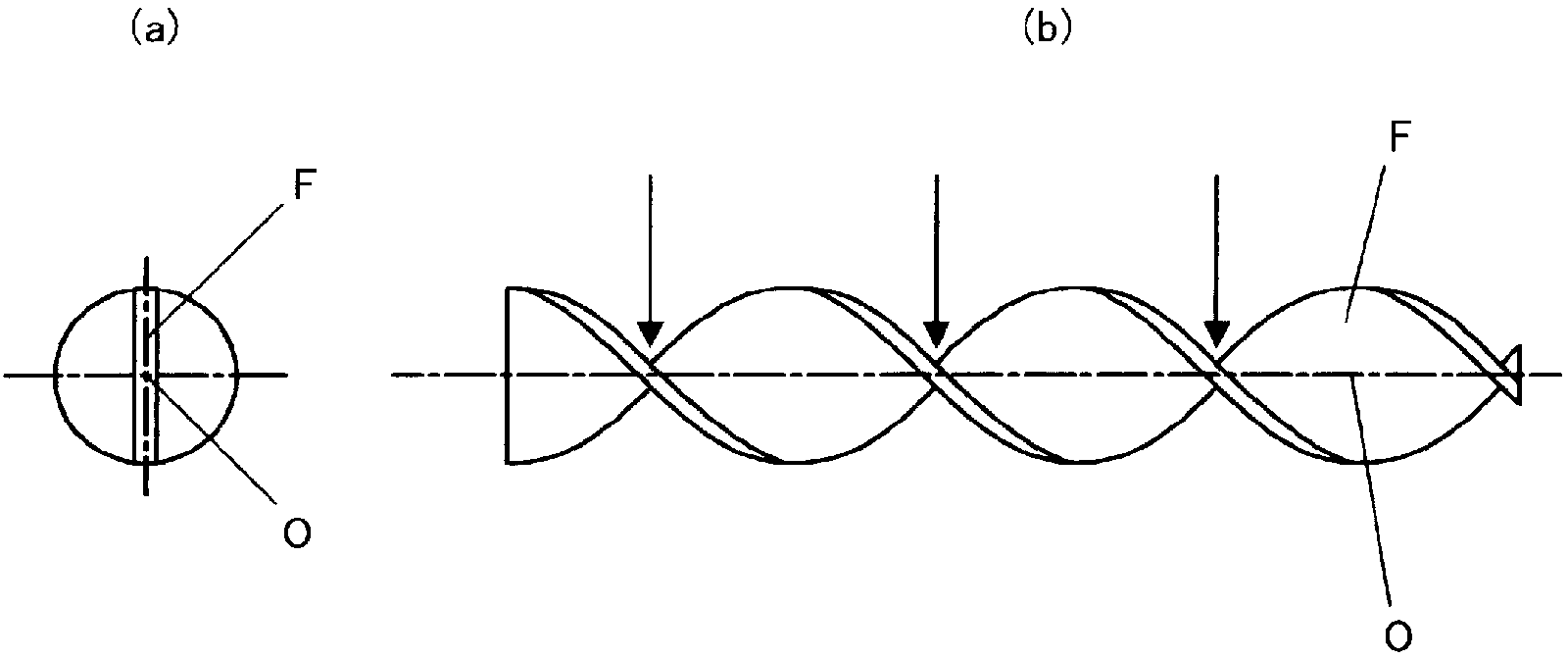
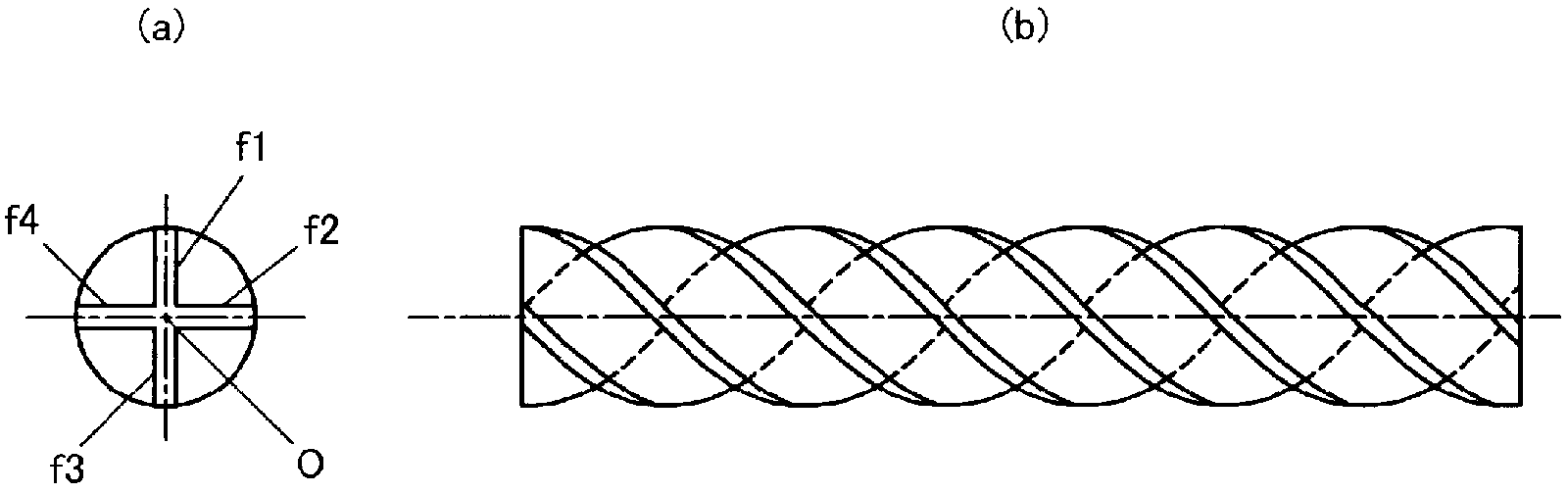
[0066] figure 2 It is a figure explaining the helical steel of this invention.

[0067] The helical steel of the present invention is formed by twisting the steel material along the central axis with an axis parallel to the long axis direction of the steel material as the central axis O, and the steel material has at least three or more long-side members (f1 to f4) relative to each other. The central axis O is radially arranged.

[0068] figure 2 (a) shows a cross-sectional view perpendicular to the long axis direction of the helical steel, figure 2 (b) shows the side view of the helical steel.

[0069] figure 1 twisted flat steel with figure 2 Compared with the spiral steel, the difference between the two is clear, in particular, there is no spiral steel figure 1 The mechanical strength of the porti...


PUM


Abstract

The purpose of the invention is to provide a spiral steel having a high mechanical strength and being capable of easily narrowing the pitch interval of a twisted portion (spiral blade portion) even without changing a twist angle and also to provide an application product of the spiral steel and a method for manufacturing the spiral steel. The spiral steel is formed in such a way that steels (f1 to f4) having, as a center axis, an axis parallel with the longitudinal direction of the steels and having a shape including at least three or more long side members disposed radially with respect to the center axis are twisted along the center axis.

Description

technical field [0001] The present invention relates to a helical steel formed by twisting a steel material of a specific shape, an applied product thereof, and a manufacturing method of the helical steel. Background technique [0002] Conventionally, twisted flat bars made by twisting flat bars are used. The applicant has proposed and practically applied various utilization methods of twisted flat steel. [0003] As specific examples, there are a pile for driving into the soil shown in Patent Document 1, a pillar in which rigidity is ensured by joining a steel pipe to a twisted flat steel shown in Patent Document 2, and an anti-floating structure shown in Patent Document 3. Anchors (tent nails), etc. These piles and the like can be easily installed by punching, and can also be easily removed by pulling out while turning. [0004] As another application of the twisted flat steel, as shown in Patent Document 4, it can be used as a drill of a hole digger, or as a conveying ...

Claims


Application Information

Patent Timeline
Patent Type & Authority Applications(China)
IPC IPC(8): B21D11/14E02D5/56E02D17/20E02D27/42F28F9/24F28F13/12
CPCF28F1/36B65G33/26B21C47/02F28D7/106F28D7/12B01F7/00425B21D53/02B21D11/14F28F1/00F28F13/12F28D7/103E21B10/00E02D5/801E02D5/285F16L9/02E02D5/56B01F27/1144
Inventor 后藤常郎
Owner 后藤常郎
Why Eureka
Try Eureka