Sampler circuit

A sampler and circuit technology, applied in the demodulation of oscillation sampling angle, circuits that oscillate independently of each other, electrical components, etc., can solve problems such as metastability effects, hysteresis, and the insensitivity of digital phase detectors

Active Publication Date: 2013-06-05
GUANGDONG OPPO MOBILE TELECOMM CORP LTD
View PDF4 Cites 11 Cited by
  • Summary
  • Abstract
  • Description
  • Claims
  • Application Information

AI Technical Summary

Problems solved by technology

State-of-the-art digital phase detectors are susceptible to metastability problems due to the asynchronous relationship between the sampling clock and the sampled reference clock
Furthermore, known digital phase detectors are not very sensitive and they suffer from hysteresis and dead band / dead time due to regenerative gain

Method used


Image

  • Sampler circuit
  • Sampler circuit
  • Sampler circuit

Examples


Embodiment Construction

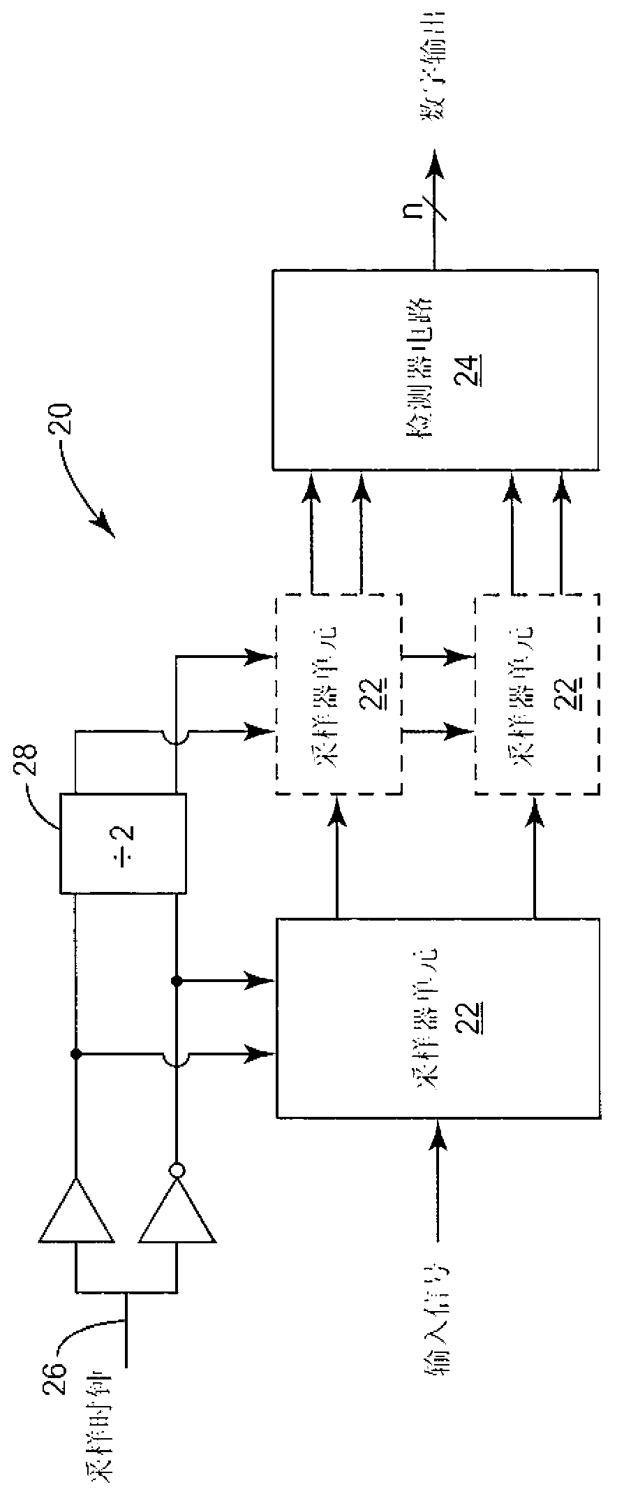
[0020] In a DPLL, the reference clock and DCO output are asynchronous to each other. In fact, the two signals are locked to each other only by DPLL corrective action. Thus, sampling the reference clock with a clock derived from the DCO output raises significant metastability concerns. The phase difference between these two clocks is constantly changing. When the phase difference is close to 0, there are brief durations in which it is not clear whether the sampled value is a logic 0 or a logic 1. In a practical implementation, this duration is actually a small time window for which the correct level of the sampled signal cannot be properly resolved. This is called the metastability window.

[0021] Most sampler circuits employ some form of regenerative feedback to derive a logic 0 or a logic 1 from the sampled input signal. The speed at which a regenerative circuit can resolve an input signal as a logic 0 or a logic 1 depends exponentially on the magnitude of the input sign...


PUM


Abstract

A sampler circuit comprises a plurality of series-connected sampler cells and a detector circuit. Each successive stage comprises twice the number of sampler cells, in parallel, as the previous stage, and is clocked at half the sampling frequency of the previous stage. Each sampler cell comprises two parallel branches of series-connected clocked inverters. A clocked inverter is operative to invert an applied signal during one phase of an applied sampling clock, and to render a high impedance output during the other sampling clock phase. Successive clocked inverters are clocked with opposite (i.e., positive/negative) versions of the sampling clock. The detector circuit examines the outputs of the last stage of sampler cells, and may for example comprise an OR function to detect a state transition in an applied input signal. The sampler circuit exhibits immunity to metastability and low power consumption.

Description

[0001] This application claims U.S. Provisional Patent Application Serial No. 61 / 388,302, filed September 30, 2010, entitled "Reference Clock Sampler Circuit for Digital PLL" and Priority Claim to U.S. Utility Model Patent Application entitled "Reference Clock Sampler Circuit for Digital PLL," filed August 4, 2011, the disclosure of which is adopted by All references are incorporated herein. Co-pending U.S. Patent Application Serial No. _, entitled "Reference Clock Sampling Digital PLL," assigned to the assignee of this application and filed herewith, is hereby incorporated by reference in its entirety merged here. technical field [0002] The present invention relates generally to sampling circuits, and more particularly to a clocked inverter sampler circuit in which metastability is substantially eliminated. Background technique [0003] A sampler circuit is a circuit that determines the state of an applied signal by rapidly quantizing or sampling the signal and processi...

Claims


Application Information

Patent Timeline
Patent Type & Authority Applications(China)
IPC IPC(8): H03L7/091H03D13/00
CPCH04L7/0337H03L7/091H03D3/006H03L2207/50H03D13/00
Inventor 保罗·马特曼约翰内斯·柏图斯·安东尼乌斯·弗拉姆巴赫
Owner GUANGDONG OPPO MOBILE TELECOMM CORP LTD
Why Eureka
Try Eureka