Dismountable locking mechanism of drawer slide rail and side plate

A technology of locking mechanism and side plate

Active Publication Date: 2013-06-12
伍志勇
View PDF7 Cites 73 Cited by
  • Summary
  • Abstract
  • Description
  • Claims
  • Application Information

AI Technical Summary

Problems solved by technology

It is said that this structure is equipped with a lever-type lock bar on the connecting seat to fasten and connect with the drawer slide rail. Its locking force is large, and it has the characteristics of quick assembly and low manufacturing cost; Complicated, high manufacturing cost, it must be assembled under the bottom plate through other fixing parts during installation, which not only increases the load capacity of the drawer, but also the whole mechanism must be disassembled and replaced in case of damage, high maintenance cost and cumbersome disassembly process

Method used


Image

  • Dismountable locking mechanism of drawer slide rail and side plate
  • Dismountable locking mechanism of drawer slide rail and side plate
  • Dismountable locking mechanism of drawer slide rail and side plate

Examples


no. 1 example

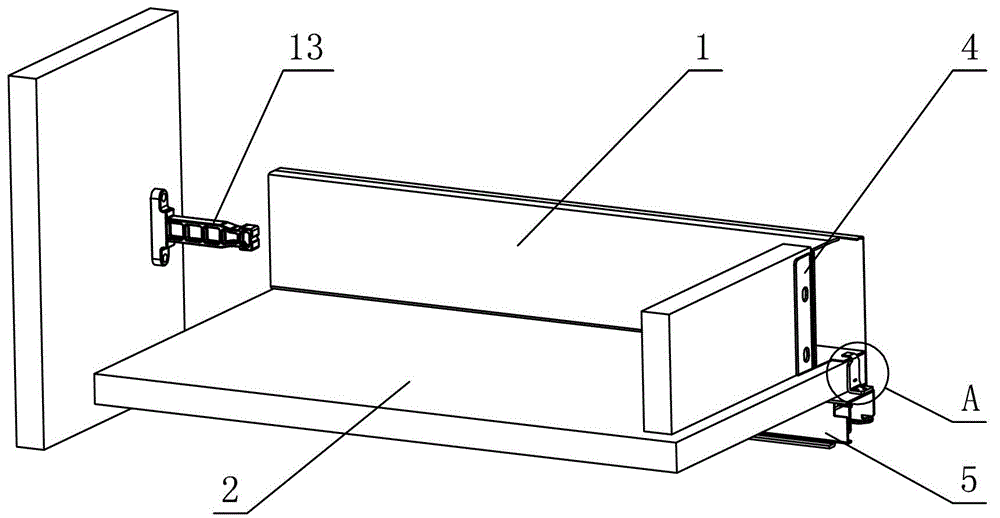
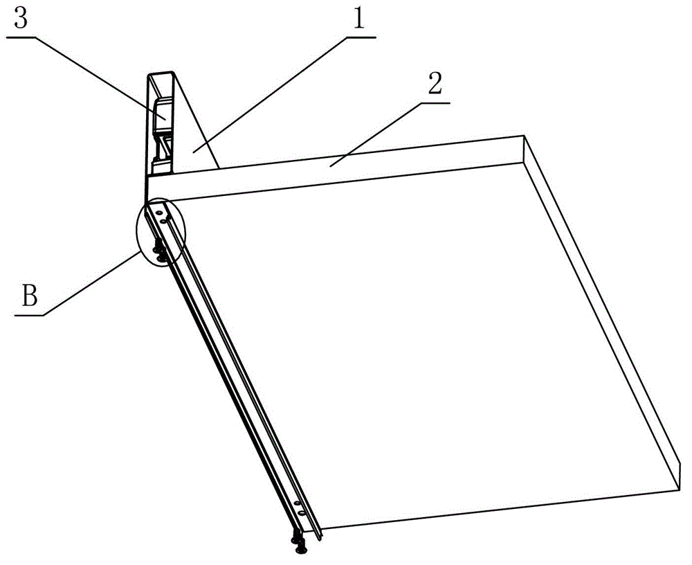
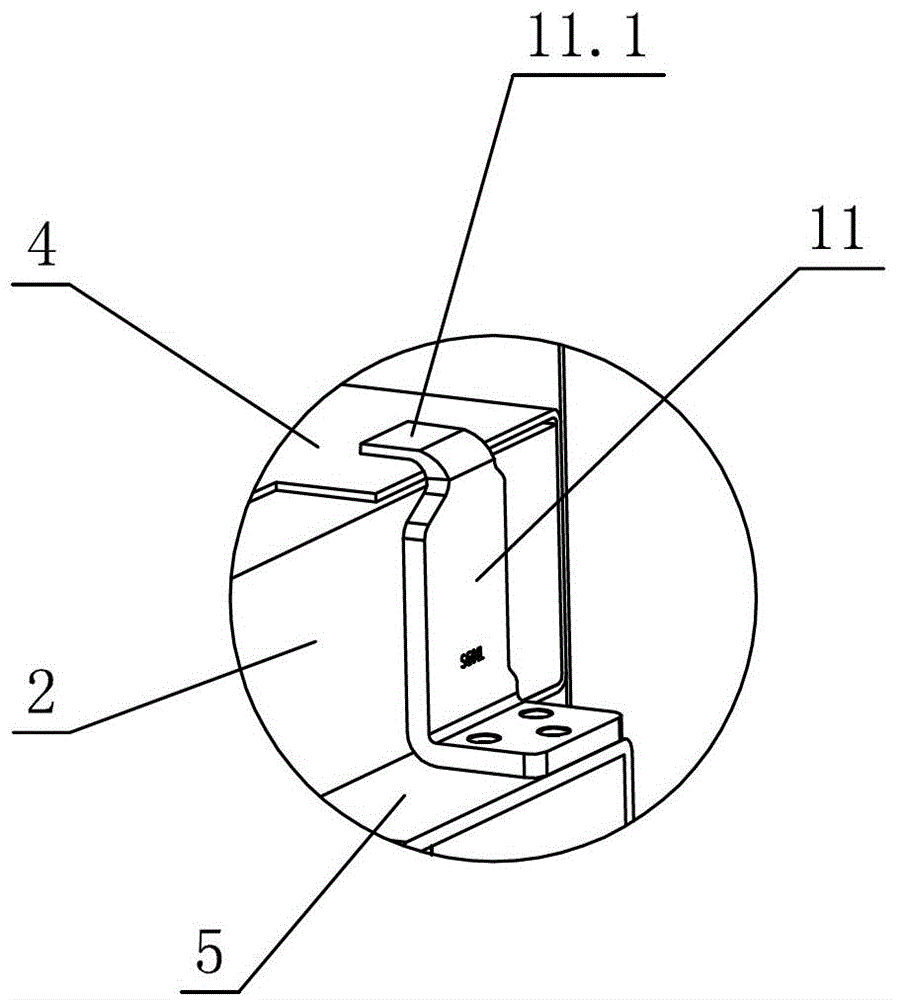
[0031] see Figure 1-Figure 14 , the detachable locking mechanism of the drawer slide rail and the side plate, including the side plate 1, the bottom plate 2 and the slide rail assembly for opening and closing the drawer, the side plate 1 is provided with the front connecting piece 3 connected to the front panel, connected The rear connector 4 of the back panel is characterized in that the side plate 1 is provided with a slot 1.1 for accommodating the bottom plate 2, and the bottom plate 2 is arranged on the slot 1.1, and acts on the moving slide rail 5 of the slide rail assembly, and the side The inner wall of the plate 1 is at least partly vertical, and transitions with the slot 1.1 at right angles, chamfers, arcs or a combination thereof; a detachable locking mechanism is provided between the side plate 1 and the movable slide rail 5, and the movable slide rail 5 It is detachably connected with the side plate 1 through a locking mechanism.

[0032] The locking mechanism is...

no. 2 example

[0039] see Figure 15 , Figure 16 , the detachable locking mechanism of the drawer slide rail and the side panel is different from the first example in that: the locking bolt 7 is provided with a convex pin 7.6 or a concave part; the lock piece 6 is provided with a pillar 6.7, and through The pillar 6.7 is rotatably connected with a lever 12, and the middle part of the lever 12 is provided with a positioning hole 12.1 corresponding to the pillar 6.7. Or the convex part is matched and connected, and the other end is provided with a boss 12.3. When the user needs to disassemble the locking mechanism, he only needs to turn the boss 12.3 on the lever 12 to drive the lock tongue 7 to slide into the cavity 6.3, then the locking mechanism and the moving slide rail 5 can be separated, and the adjustment lock can be saved through the lever principle. The force of the tongue 7 is strong in practicability.

[0040] In this embodiment, the elastic member 8 can be replaced by a torsion...


PUM


Abstract

The invention relates to a dismountable locking mechanism of a drawer slide rail and a side plate. The dismountable locking mechanism comprises a side plate, a bottom plate and a slide rail assembly used for opening and closing a drawer, wherein a front connecting element for connecting a front panel and a back connecting element for connecting a rear back plate are arranged on the side plate, a groove position for accommodating the bottom plate is arranged in the side plate, the bottom plate is arranged on the groove position and acts on a movable slide rail of the slide rail assembly, a dismountable locking mechanism is arranged between the side plate and the movable side rail, and the movable side rail is detachably connected with the side plate through the locking mechanism. The dismountable locking mechanism has the advantages that the groove position used for fixing the bottom plate is arranged in the side plate, the bottom plate directly acts on the movable slide rail after the assembly is completed, the drawer stress is more uniform, the work loss of each component is smaller, the service life is longer, the inner wall of the side plate is vertical, the thickness of the side plate is effectively reduced, the use space of the drawer is increased, in addition, the side plate and the movable side rail are detachably connected through the dismountable locking mechanism, the dismounting and the mounting of the side plate and the movable slide rail are fast and convenient, the manufacture and maintenance cost is low, the integral design of the drawer is favorably realized, and the drawer is tidier and more attractive.

Description

technical field [0001] The invention relates to a drawer, in particular to a detachable locking mechanism for a drawer slide rail and a side plate. Background technique [0002] Chinese Patent Document No. CN102326978A disclosed on January 25, 2012 a lock adjustment mechanism for drawer slide rails. It includes a coupling seat arranged on the bottom surface of the drawer, and a locking bar is rotatably connected to the coupling seat. One end of the locking bar There is a lock tongue and a fastening connection with the slide rail, and the other end extends out of the handle, and the lock tongue is separated from the slide rail by pressing the handle; the lock tongue is provided with an inclined guide surface corresponding to the slide rail, and the rear of the guide surface is a stepped lock The stepped locking part is fastened and connected with the lock hole provided by the slide rail. The number of steps in the stepped locking part is more than two; the locking rod is set ...

Claims


Application Information

Patent Timeline
Patent Type & Authority Applications(China)
IPC IPC(8): A47B88/08F16B5/00F16B12/10A47B88/49
Inventor 伍志勇
Owner 伍志勇
Why Eureka
Try Eureka