Bar Conveyor

A conveyor and bar technology, applied in the direction of conveyor objects, transportation and packaging, can solve the problems of high labor intensity, high equipment cost and low efficiency, and achieve the effect of improving the degree of automation and production efficiency and reducing labor intensity.

Inactive Publication Date: 2016-01-20
XIAMEN LANGUAN AUTOMATION TECH
View PDF5 Cites 0 Cited by
  • Summary
  • Abstract
  • Description
  • Claims
  • Application Information

AI Technical Summary

Problems solved by technology

[0002] At present, in the production process, if it is necessary to produce and process small bars with circular cross-sections, it mainly relies on manual feeding one by one or tedious manual swinging, especially for those ultra-slender bars (such as: The diameter is less than 1mm, the length-to-diameter ratio exceeds 1:100, or even as high as 1:2000), the bars are intertwined, and it is difficult to complete the automatic feeder by means of vibration, general mechanical separation, and manipulator grabbing. take, deliver
The disadvantages of traditional operation methods are: high labor intensity and low efficiency, only one person can operate one machine, and automatic production cannot be realized
At present, the existing automatic feeding machines on the market can realize automatic feeding, but most of them need to replace parts such as pallets or perform more professional mechanical adjustments to achieve specification conversion.
In this way, many pallets need to be equipped according to the material specifications, resulting in high equipment costs; or it is difficult for ordinary operators to complete the specification conversion, and it needs to be adjusted by technicians, which is not conducive to efficient production

Method used


Image

  • Bar Conveyor
  • Bar Conveyor
  • Bar Conveyor

Examples


Embodiment 1

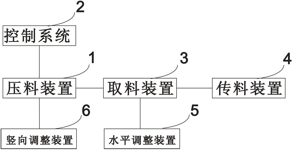
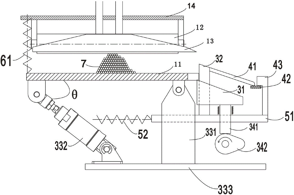
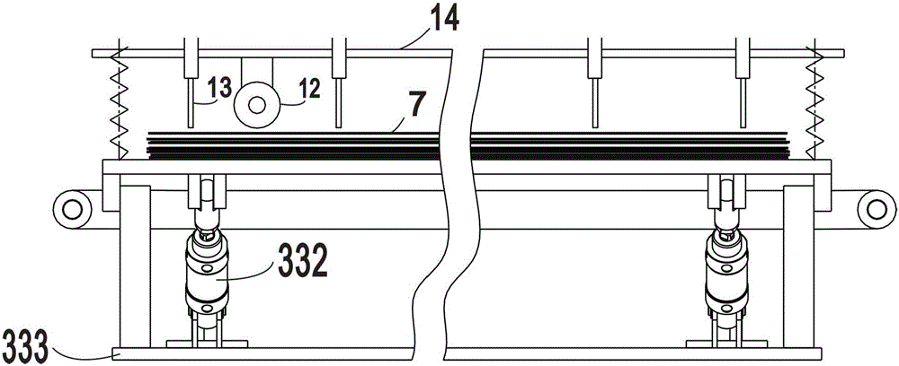
[0022] see figure 1 , figure 2 and image 3 , a bar conveyor, including a pressing device 1 for arranging the whole pile of multi-layer bars 7 into a single layer arrangement, a control system 2 for automatically controlling the pressing device, and a A retrieving device 3 for automatic single-root retrieving in the material device, a material transfer device 4 for transferring material from the reclaiming device, and an adjustment device for adjusting the bar specification; the adjustment device includes a bar specification The horizontal adjustment device 5 and the vertical adjustment device 6, the horizontal adjustment device 5 is connected with the material taking device 3, and the vertical adjustment device 6 is connected with the pressing device 1.

[0023] The pressing device 1 includes a tray 11 for placing the whole pile of multi-layer bars, a monolithic bar 12 for arranging the whole pile of multi-layer bars 7 into a single-layer arrangement, and a single-layer ar...

Embodiment 2

[0036] The difference from Embodiment 1 is that the reclaiming power device includes a power screw (not shown) connected to the reclaiming fork, and a second cylinder (not shown) for driving the power screw to move up and down Or a motor (not shown), so that the up and down motion of the reclaiming fork is driven by the second cylinder or the motor driving the power screw mandrel.

Embodiment 3

[0038] see Figure 5 , different from Embodiment 1, the level adjustment device includes a horizontal slide plate 51, a horizontal screw rod 52 fixedly connected with the horizontal slide plate, a graduated handwheel 53 connected with the horizontal screw rod, which can be achieved through low-cost Scaled handwheel for quick and accurate adjustment of individual extractions for bar sizes.


PUM


Abstract

The invention provides a bar conveyor, which comprises a bar pressing device, a control system, a bar taking device, a bar transferring device and an adjusting device, wherein the bar pressing device is used for arranging batches of multilayer bars into a single layer; the control system is used for controlling the bar pressing device automatically; the bar taking device is used for taking a single piece of bar automatically from the bar pressing device; the bar transferring device is used for transferring bars from the bar taking device; the adjusting device is used for adjusting the bar specifications and comprises a horizontal adjusting device and a vertical adjusting device for the bar specifications; the horizontal adjusting device is connected with the bar taking device; and the vertical adjusting device is connected with the bar pressing device. According to the bar conveyor, manual bar taking and storage are replaced, the labor intensity of workers is reduced greatly, and the automation degree and the production efficiency are improved greatly. During the production process, bars having different specifications are adjusted through the adjusting device, thereby solving the problems that an existing bar conveyor cannot convey extremely slender bars, sizes of bars for production cannot be adjusted freely, and the like.

Description

technical field [0001] The invention relates to the field of mechanical equipment, in particular to a bar conveyor. Background technique [0002] At present, in the production process, if it is necessary to produce and process small bars with circular cross-sections, it mainly relies on manual feeding one by one or tedious manual swinging, especially for those ultra-slender bars (such as: The diameter is less than 1mm, the length-to-diameter ratio exceeds 1:100, or even as high as 1:2000), the bars are intertwined, and it is difficult to complete the automatic feeder by means of vibration, general mechanical separation, and manipulator grabbing. Take and deliver. The disadvantages of traditional operation methods are: high labor intensity and low efficiency, only one person can operate one machine, and automatic production cannot be realized. At present, the existing automatic feeding machines on the market can realize automatic feeding, but most of them need to replace pa...

Claims


Application Information

Patent Timeline
Patent Type & Authority Patents(China)
IPC IPC(8): B65G47/14B65G47/04
Inventor 林荣文
Owner XIAMEN LANGUAN AUTOMATION TECH
Why Eureka
Try Eureka