Multi-purpose self-return positioning door shaft

An automatic return and multi-purpose technology, which is applied in door/window accessories, switches with braking devices, buildings, etc., can solve the problem that the hydraulic oil viscosity of the floor spring is greatly affected, the rotating shaft device cannot be realized, and the use effect is not enough Ideal and other problems, to achieve the effect of prolonging the service life, solving the problems of hydraulic oil leakage and cam wear, and convenient processing

Inactive Publication Date: 2013-06-12
初恒毅
View PDF8 Cites 9 Cited by
  • Summary
  • Abstract
  • Description
  • Claims
  • Application Information

AI Technical Summary

Problems solved by technology

[0002] At present, floor springs are generally used as the control device for two-way free doors in buildings. The inside of the floor spring is a hydraulic cam structure. The cam device requires high machining accuracy during production and requires precision machine tools for processing. The production cost is high. The viscosity of the hydraulic oil in the spring is greatly affected by temperature, and its performance will decrease in winter when the temperature is low
The floor spring shell needs to be kept sealed to prevent the internal hydraulic oil from leaking out. However, due to wear and excessive pressure, the floor spring products currently on the market often leak oil from the shell after a period of use, which affects the use. life
The applicant once applied for an invention patent on January 11, 2008, title: a free door controller, patent number: 200810001843.8, authorization announcement date: February 16, 2011, authorization announcement number: CN 101200989 B, the The invention proposes a technical solution of a free door controller composed of an upper shaft rotation control device and a lower shaft positioning device, which is small in size, light in weight, simple in structure and easy to install, which can replace the floor springs and skylights currently used in free doors. Shaft pin; the upper shaft rotation control device includes a housing, a speed regulating damping device, an elastic splint, a rotating connecting arm and a rotating shaft, etc. The disadvantage of the upper shaft rotation control device is that its elastic splint device cannot generate enough force , The rotating shaft device cannot realize the limit function of the door shaft, so the use effect is not ideal

Method used


Image

  • Multi-purpose self-return positioning door shaft
  • Multi-purpose self-return positioning door shaft
  • Multi-purpose self-return positioning door shaft

Examples


Embodiment Construction

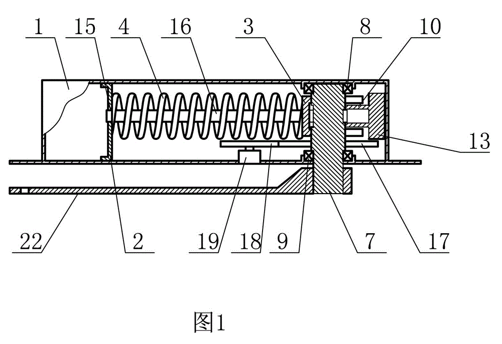
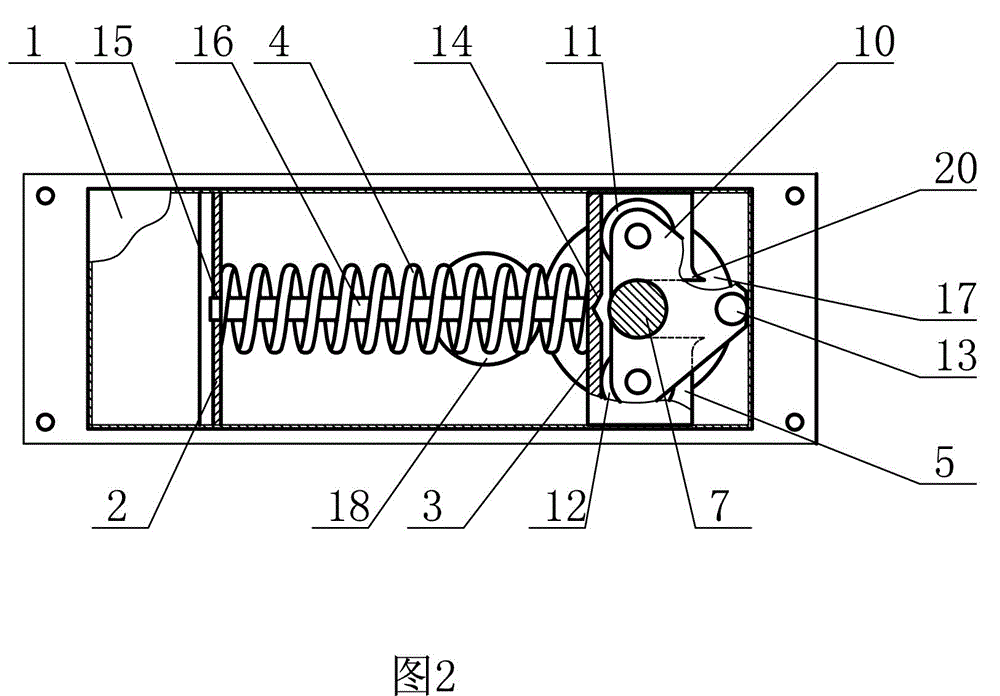
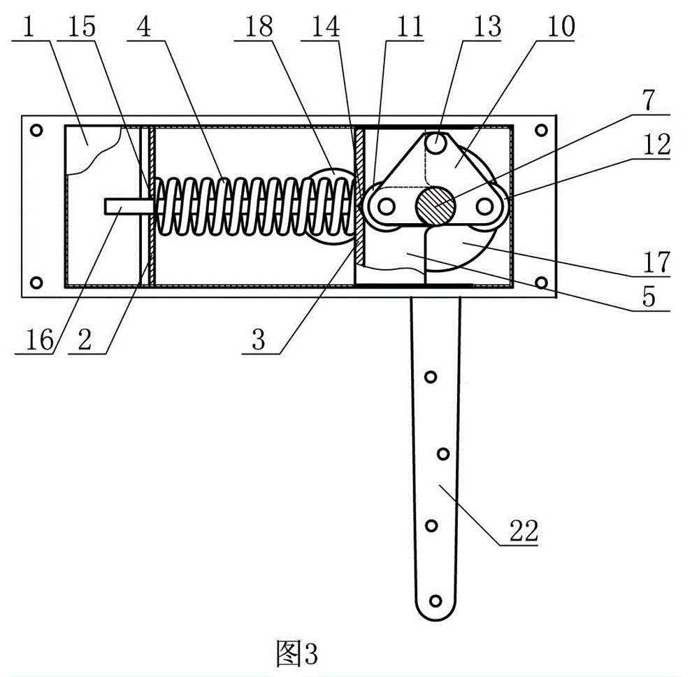
[0007] The multi-purpose automatic return positioning door shaft of the present invention includes a housing 1, a fixed seat 2 and a movable plate 3 are installed in the housing 1, a spring 4 is installed between the fixed seat 2 and the movable plate 3, and the movable plate 3 and the guide device connection, a positioning groove 14 is set on the movable plate 3, a side plate 5 is installed on the movable plate 3, a through groove 6 is set on the side plate 5, the rotating shaft 7 is connected with the housing 1 through the first bearing 8 and the second bearing 9, and the first bearing 8 is located at one end of the rotating shaft 7, the second bearing 9 is located at the middle of the rotating shaft 7, the other end of the rotating shaft 7 passes out of the casing 1, a rotating bracket 10 is installed on the rotating shaft 7, and a first roller 11, a second roller 12 and Boss 13. The present invention can be installed on the top of the door body as the upper door shaft of t...


PUM


Abstract

The invention discloses a multi-purpose self-return positioning door shaft which comprises a shell. The shell is internally provided with a permanent base and a moveable plate. A spring is installed between the permanent base and the moveable plate. The moveable plate is connected with a guide device. The moveable plate is provided with a positioning slot and a side plate which is provided with a through slot. A rotary shaft is connected with the shell through a first bearing and a second bearing. The first bearing is located at one end of the rotary shaft and the second bearing is located in the middle of the rotary shaft. The other end of the rotary shaft is threaded out of the shell, a rotary bracket is installed on the rotary shaft, and a first roller, a second roller and a convex pillar are installed on the rotary bracket. The multi-purpose self-return positioning door shaft provided by the invention has the advantages that a bidirectional free door has the functions of starting positioning, self-returning and limiting, and is simple in structure, agile to open and close, accurate to position, convenient to process, low in production cost, long in service life and the like.

Description

technical field [0001] The invention relates to a door control device for building, in particular to a multi-purpose automatic return positioning door shaft. Background technique [0002] At present, floor springs are generally used as the control device for two-way free doors in buildings. The inside of the floor spring is a hydraulic cam structure. The cam device requires high machining accuracy during production and requires precision machine tools for processing. The production cost is high. The viscosity of the hydraulic oil in the spring is greatly affected by temperature, and its performance will decrease in winter when the temperature is low. The floor spring shell needs to be kept sealed to prevent the internal hydraulic oil from leaking out. However, due to wear and excessive pressure, the floor spring products currently on the market often leak oil from the shell after a period of use, which affects the use. life. The applicant once applied for an invention pat...

Claims


Application Information

Patent Timeline
Patent Type & Authority Applications(China)
IPC IPC(8): E05F1/12E05F5/06E05D11/06
Inventor 初恒毅初跃峰初大千
Owner 初恒毅
Why Eureka
Try Eureka