System and method for controlling engine cooling circulation system

An engine cooling and circulation system technology, applied in the field of vehicles, can solve the problems of reducing the life of the supercharger, unable to warm up the engine, and no longer circulating the coolant, so as to reduce energy consumption and emissions, reduce fuel consumption and emissions, and ensure The effect of the service life

Inactive Publication Date: 2013-06-12
GREAT WALL MOTOR CO LTD
View PDF3 Cites 7 Cited by
  • Summary
  • Abstract
  • Description
  • Claims
  • Application Information

AI Technical Summary

Problems solved by technology

[0005] (1) Since the control system of the existing engine cooling cycle system cannot warm up the engine well at the initial stage of vehicle startup, resulting in a long warm-up time for cold start, high fuel consumption during warm-up, and harmful substances in the emissions High content;
[0006] (2) Only through the thermostat to control the size and circulation of the coolant through the thermostat, it is impossible to adjust the temperature of the coolant according to the operating conditions of the engine, resulting in the engine being at its best only in a narrow range of operating conditions The operating conditions under other working conditions are not ideal;
[0007] (3) Since the water pump in the cooling circulation system is controlled by the engine, after the engine stops, the water pump also stops running, and the coolant no longer circulates, so the supercharger cannot be effectively cooled and the life of the supercharger is reduced

Method used


Image

  • System and method for controlling engine cooling circulation system
  • System and method for controlling engine cooling circulation system
  • System and method for controlling engine cooling circulation system

Examples


Embodiment 1

[0048] Embodiment one Control System of Engine Cooling Circulation System

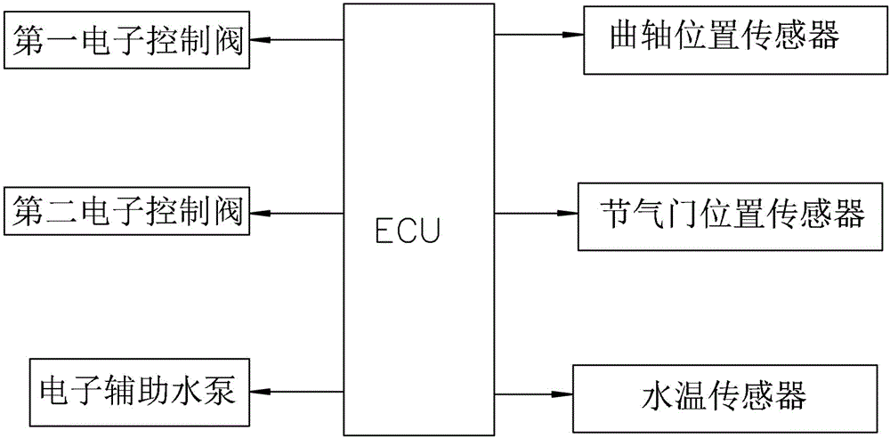
[0049] This embodiment provides a control system of the engine cooling cycle system, its structure is as follows figure 1 shown, including:

[0050] ① The main control unit, as the control center of the entire system, stores corresponding programs inside. In order to simplify the structure and save costs, this embodiment directly uses the vehicle ECU as the main control unit.

[0051] ② The detection mechanism is used to detect the vehicle engine information in real time, and transmit the detected information to the vehicle ECU connected to its signal output terminal in real time. The detection mechanism in this embodiment adopts common crankshaft position sensor, throttle position sensor, and temperature sensor, wherein the crankshaft position sensor detects the crankshaft position information of the engine in real time, and transmits the detected information to the vehicle ECU in real time; the t...

Embodiment 2

[0057] Embodiment two A control method for an engine cooling cycle system

[0058] A method for controlling an engine cooling cycle system in this embodiment is realized by the control system for an engine cooling cycle system provided in Embodiment 1.

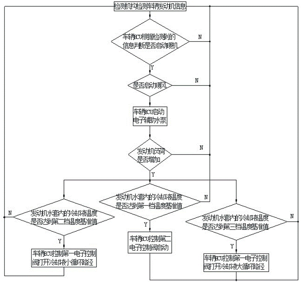
[0059] like image 3 As shown, the control method of this embodiment includes the following steps:

[0060] (1) Information detection: The detection mechanism detects the information of the vehicle and the engine in real time, and transmits the detected information to the main control unit in real time.

[0061] (2) Control the action of the actuator: the main control unit analyzes the current operating status of the vehicle engine based on the received information, and controls the actuator to perform corresponding actions according to the control strategy of the actuator under the various operating conditions of the vehicle engine stored by itself.

[0062] Wherein, in the step (2), the control of the actuator by the ma...


PUM


Abstract

The invention relates to a system for controlling an engine cooling circulation system; the system comprises a main control unit, a detection mechanism and an actuating mechanism, wherein the main control unit is taken as a control center, and a corresponding program is stored in the main control unit; the detection mechanism is used for detecting vehicle signals and transmitting the detected information into the main control unit connected with a signal output end of the detection mechanism in real time; and the actuating mechanism is used for executing a control command, receiving control signals which are sent out by the main control unit connected with the actuating mechanism and correspondingly controlling the cooling circulation system. The invention also relates to a method for controlling the engine cooling circulation system. The control system and the control method are simple, and can be used for controlling the cooling liquid circulation path according to the different running conditions of an engine, thus guaranteeing the engine to run well and reducing the energy consumption and the emission of the engine; and furthermore, after the engine stops, an electronic auxiliary water pump can be continuously used for cooling the cooling liquid effectively, so that the service life of a booster is prolonged. The system and the method are suitable for various vehicle engines.

Description

technical field [0001] The invention belongs to the field of vehicles, and relates to a cooling cycle system of an engine, in particular to a control system and a corresponding control method of the engine cooling cycle system. Background technique [0002] With the depletion of oil, the price of oil has been increasing in recent years. At the same time, the exhaust gas emitted by vehicles has made air pollution more and more serious. At present, various automobile manufacturers are committed to the research and development of energy-saving and emission-reducing vehicles. Among them, optimizing The control of the cooling cycle system of the engine is one of the effective measures for energy saving and emission reduction. [0003] During the cold start and warm-up process of the engine, due to the low temperature of the engine, the combustion condition in the cylinder is poor, resulting in high fuel consumption and poor emission of the engine at this time; at the same time, w...

Claims


Application Information

Patent Timeline
IPC IPC(8): F01P7/14
Inventor 关松胡远航段景辉魏洪伟贾殿臣高峰刘义佳
Owner GREAT WALL MOTOR CO LTD
Why Eureka
Try Eureka