

Bayonet vehicle image identification method based on image features
An image feature and image recognition technology, which is applied in the field of bayonet vehicle image recognition based on image features, can solve the problem of high computational complexity, and achieve the effects of high recognition accuracy, fine classification and improved accuracy.
- Summary
- Abstract
- Description
- Claims
- Application Information
AI Technical Summary
Problems solved by technology
Method used
Image

Examples
Embodiment 1
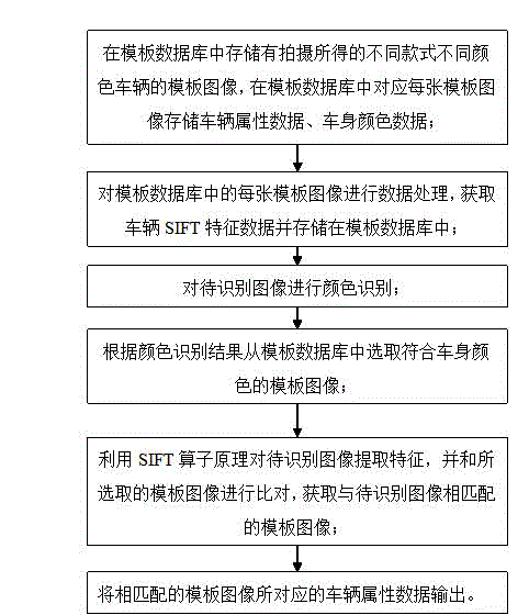
[0060] Such as figure 1 Shown is a flow chart of a specific embodiment of a bayonet vehicle image recognition method based on image features in the present invention. Referring to example 1, the specific steps of a kind of image feature-based bayonet vehicle image recognition method of this specific embodiment include:
[0061] Step S100: Establish template database:
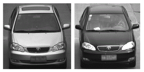
[0062] Step S101: Store template images of vehicles of different styles and colors captured in the template database, and store vehicle attribute data and body color data corresponding to each template image in the template database, wherein the vehicle attribute data may include vehicle brand and vehicle model and the model year of the vehicle; e.g. figure 2 Shown are two template images of "Toyota, Corolla, ninth generation";
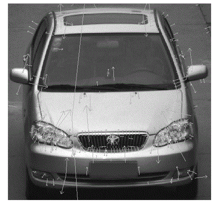
[0063] Step S102: Perform data processing on each template image in the template database, obtain vehicle SIFT feature data and store it in the template database, wherein the SIFT f...
Embodiment 2
[0100] Such as Figure 7 Shown is a flow chart of a preferred embodiment of a bayonet vehicle image recognition method based on image features in the present invention. see Figure 7 , the specific steps of this preferred embodiment are as follows:
[0101] Establish a template database: pre-store template images of different models and styles of vehicles in the template database, and store the vehicle attribute data, body color, and SIFT feature data of the template images in the template database correspondingly; wherein for each template image, its first Delimit the area where the license plate is located, and delete the SIFT feature information of each template image located in the license plate area;
[0102] When it is necessary to perform vehicle recognition on the image to be recognized, first perform color recognition on the image to be recognized, and simultaneously calculate the SIFT feature of the image to be recognized;
[0103] Input the image to be recognized...
PUM
 Abstract
Description
Claims
Application Information