Coupled feeding horizontal omni-directional annular radio frequency identification (RFID) label antenna

An RFID tag and coupling feeding technology, which is applied in the field of coupling feeding horizontal omnidirectional annular RFID tag antenna to achieve the effect of good omnidirectionality and good adjustable characteristics

Active Publication Date: 2013-06-12
ZHEJIANG UNIV
View PDF7 Cites 12 Cited by
  • Summary
  • Abstract
  • Description
  • Claims
  • Application Information

AI Technical Summary

Problems solved by technology

[0004] When the vertical side of the target object is an irregular surface or the area is not enough to provide the space for the RFID tag to be attac

Method used


Image

  • Coupled feeding horizontal omni-directional annular radio frequency identification (RFID) label antenna
  • Coupled feeding horizontal omni-directional annular radio frequency identification (RFID) label antenna
  • Coupled feeding horizontal omni-directional annular radio frequency identification (RFID) label antenna

Examples


Embodiment Construction

[0019] Below in conjunction with accompanying drawing, the present invention is described in further detail:

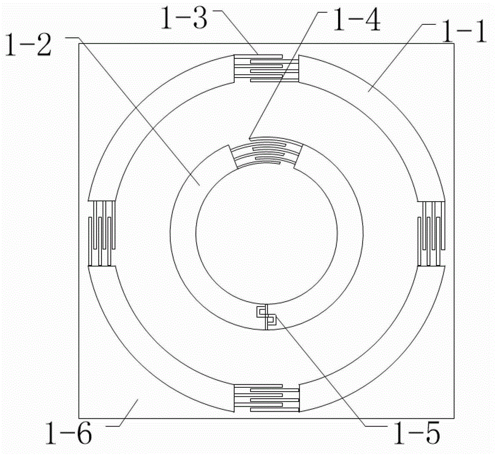
[0020] Such as figure 1 As shown, the MIMO antenna in the present invention is composed of a radiating outer loop 1-1 and a feeding inner loop 1-2. The overall size of the antenna is 43 mm × 43 mm. Substrates 1-6 are made of PET material commonly used in RFID tag processing. Its dielectric constant is 4.3 and its structural parameters are 45mm × 45mm × 0.05mm. Four interdigitated capacitors 1-3 with the same structure are periodically loaded on the outer ring, one interdigitated capacitor 1-4 is loaded on the inner ring, and RFID chips 1-5 are placed on the inner ring symmetrically to the interdigitated capacitors. The radius of the outer ring (from the center of the circle to the middle of the ring width) is 20mm, and the ring width is 3mm; the radius of the inner ring (from the center of the circle to the middle of the ring width) is 10mm, and the ring width is 3mm...


PUM


Abstract

The invention relates to a coupled feeding horizontal omni-directional annular radio frequency identification (RFID) label antenna. Existing RFID antennas are mostly in a dipole structure, the directional graph is perpendicular to the surface of the antenna and commonly applied to a vertical surface of an object, and when the vertical surface of a target object is not enough to provide an available area for an RFID label, the structure is not applicable any more. The coupled feeding horizontal omni-directional annular RFID label antenna comprises a substrate, a radiation outer ring antenna and a coupled feeding inner ring structure, wherein the radiation outer ring antenna and the coupled feeding inner ring structure are arranged on the substrate, and the two rings are in a concentric structure. The coupled feeding horizontal omni-directional annular RFID label antenna is small in structure, capable of working below the federal communications commission (FCC) frequency range (902-928 MHz), and capable of being attached to the upper surface and the lower surface of the target object, the radiation directional graph is omni-directional on a horizontal plane, and the reading distance can reach 9.5 m as far as possible.

Description

technical field [0001] The invention belongs to the field of antenna technology and wireless communication, and relates to a coupling feeding horizontal omnidirectional circular RFID tag antenna. Background technique [0002] Radio frequency identification is RFID (Radio Frequency Identification) technology, also known as electronic tags and radio frequency identification. communication technology. Commonly used passive RFIDs include low frequency (125k~134.2K), high frequency (13.56Mhz), and ultrahigh frequency (860-960MHz). [0003] As an important part of the RFID system, the RFID tag antenna's performance will greatly affect the efficiency and quality of the entire RFID system. The main factors affecting the performance of RFID antennas include antenna size, operating frequency band, impedance and gain. Commonly used RFID antennas often adopt the form of bent-line dipoles, which is convenient for reducing the size of the antenna and processing the antenna. The patter...

Claims


Application Information

Patent Timeline
IPC IPC(8): H01Q7/00H01Q1/36H01Q1/38H01Q1/50H01Q1/22
Inventor 刘琦俞钰峰何赛灵
Owner ZHEJIANG UNIV
Why Eureka
Try Eureka