Switch reluctance machine applied to elevator traction machine

A technology of switched reluctance motor and elevator traction machine, which is applied in the direction of electrical components, electromechanical devices, magnetic circuit static parts, etc., can solve the problems of poor running stability, large torque ripple, large noise and vibration, etc. Stabilization, reduced torque ripple, noise and vibration reduction effects

Inactive Publication Date: 2013-06-12
JIANGSU GENERAL ELEVATOR
View PDF0 Cites 2 Cited by
  • Summary
  • Abstract
  • Description
  • Claims
  • Application Information

AI Technical Summary

Problems solved by technology

[0004] Its disadvantages are: the torque ripple of the device is large, the running stability is poor, and the noise and vibration are large during operation.

Method used


Image

  • Switch reluctance machine applied to elevator traction machine
  • Switch reluctance machine applied to elevator traction machine
  • Switch reluctance machine applied to elevator traction machine

Examples


Embodiment Construction

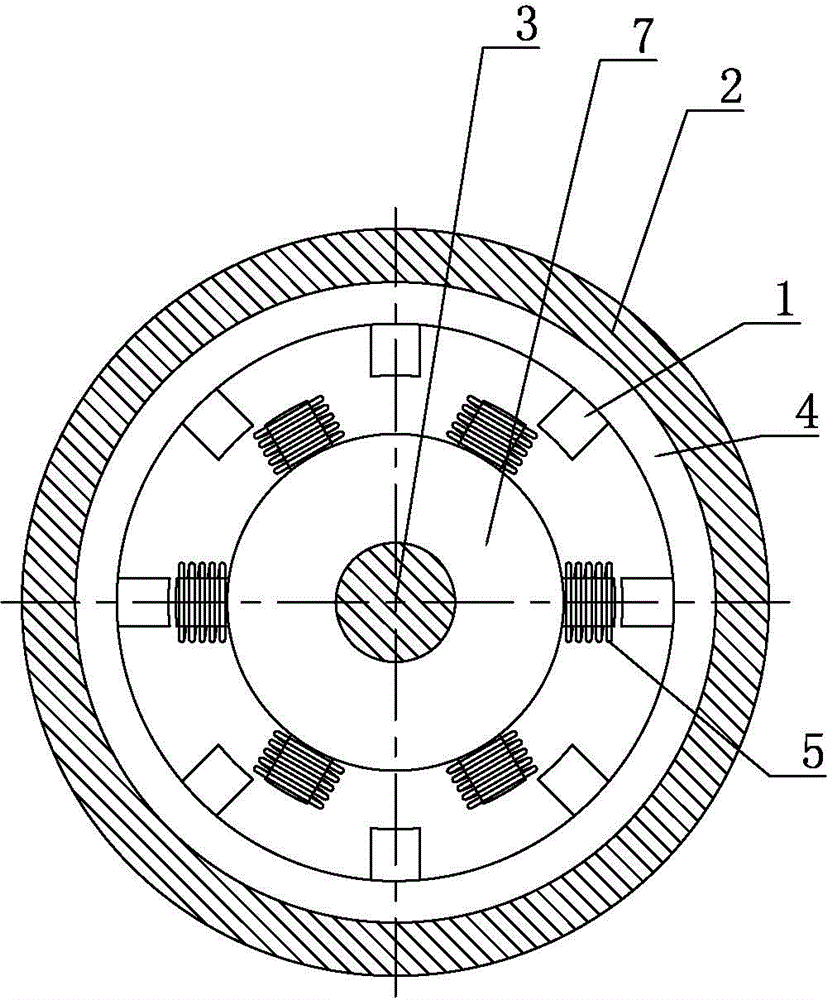
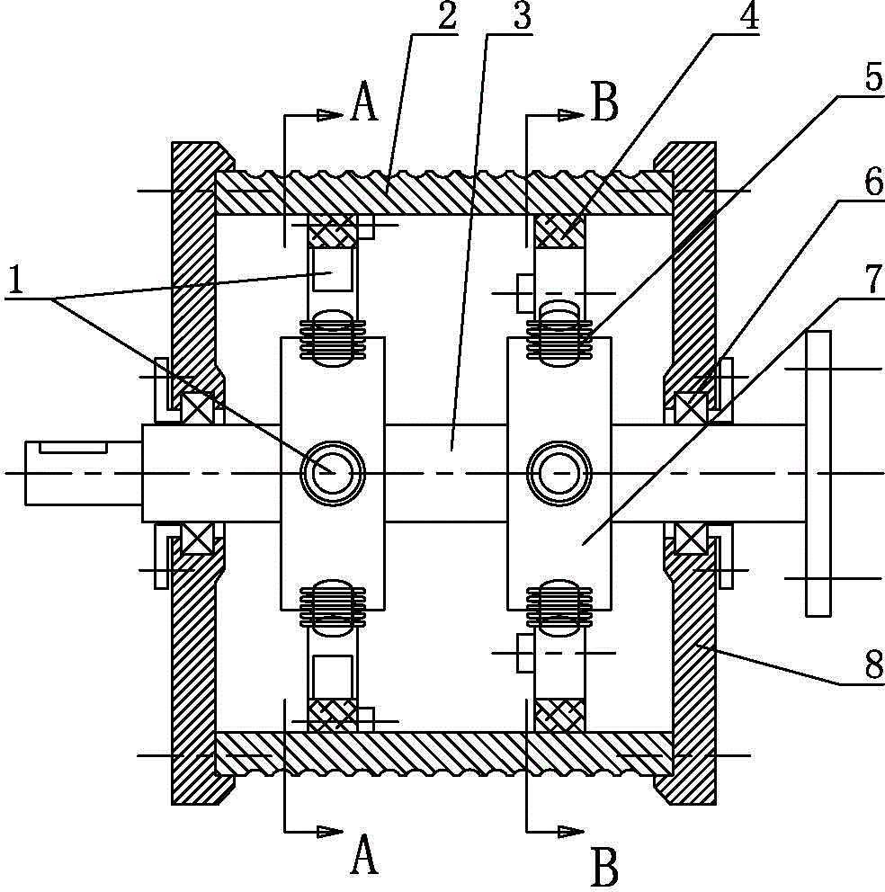
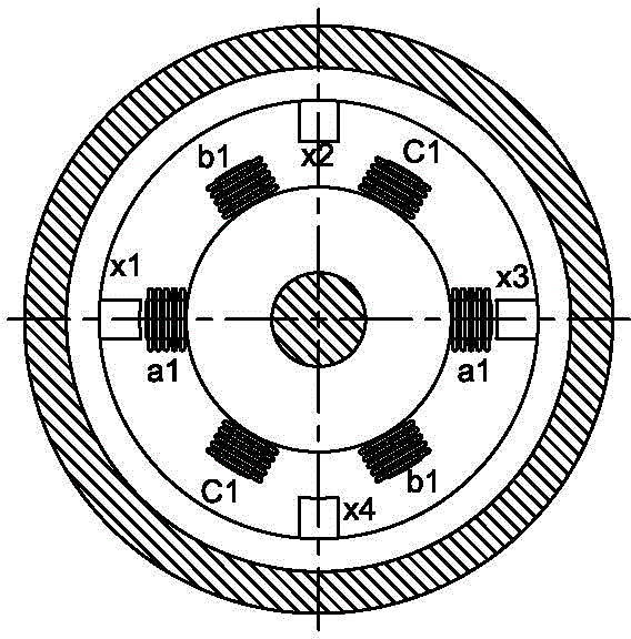
[0016] As shown in the figure, it is a switched reluctance motor for elevator traction machine, including a rotor 4 and a stator 7 which are coaxially arranged and can rotate relatively. The rotor 2 is located on the outer periphery of the stator 7, and the front and rear ends of the rotor 2 are respectively There are four radially inward tooth poles 1 uniformly distributed. The front and rear ends of the stator 7 are respectively distributed with six radially outward tooth poles 1. The front and rear ends of the stator are connected by a fixed shaft 3. The tooth poles 1 at the front and rear ends of the rotor are arranged with a phase difference of 45° in the circumferential direction. The tooth poles 1 at the front and rear ends of the stator are arranged in the same phase in the circumferential direction. The stator teeth are wound with coils 5, which are diametrically opposed. The coils 5 on the two tooth poles are arranged in series; the rotor 4 is provided with a steel wir...


PUM


Abstract

The invention discloses a switch reluctance machine applied to an elevator traction machine in the technical field of motors. The switch reluctance machine comprises a rotor and a stator, wherein the rotor and the stator are coaxially arranged and can relatively rotate, the rotor is arranged on the outer circumference of the stator, four tooth poles with inward radial directions are uniformly distributed on the front end and the back end of the rotor, six tooth poles with outward radial directions are correspondingly and uniformly distributed on the front end and the back end of the stator, the phase difference of the tooth poles of the front end and the back end of the stator are 45 degrees in the circumference direction, the tooth poles of the front end and the back end of the stator are in same-phase arrangement in the circumference direction, a coil is wound around each tooth pole of the stator, and the coils of the two tooth poles with the opposite radial directions are in serial arrangement. When the switch reluctance machine works, each phase coil is sequentially communicated with a power supply to generate the magnetic flux, a magnetic line of force passes through an iron core of the rotor from the nearest tooth pole of the rotor, and the rotor can rotate in one direction under the traction of the magnetic force. The switch reluctance machine disclosed by the invention can reduce the torque ripple of the rotor so that the rotor stably operates and the noise and the vibration of the rotor during operation are greatly reduced; and the switch reluctance machine can be served as the elevator traction machine.

Description

Technical field [0001] The invention relates to a motor, in particular to a motor for an elevator traction machine. Background technique [0002] In the prior art, there is a switched reluctance motor in which the stator iron core has six tooth poles and the rotor iron core has four tooth poles, all of which are punched and laminated from silicon steel sheets with good magnetic conductivity. There is a gap between the rotor and the stator, and the rotor can rotate freely in the stator. Since both the stator and the rotor have convex teeth, this form is also called a double salient pole structure. A coil (stator winding) is wound on the stator teeth, which is an excitation winding that provides a working magnetic field to the motor, and there is no coil on the rotor. [0003] The switched reluctance motor uses the principle of minimum reluctance, that is, the magnetic flux is always closed along the path with the least reluctance, and the attraction between the tooth poles pulls t...

Claims


Application Information

Patent Timeline
Patent Type & Authority Applications(China)
IPC IPC(8): H02K29/03H02K1/14H02K3/28
Inventor 陈晓进谢晓纪郑鑫曹建新
Owner JIANGSU GENERAL ELEVATOR
Why Eureka
Try Eureka