Distributed beam forming system and carrier synchronization method of transmitting antennas at source end of distributed beam forming system

A technology of beam synthesis and carrier synchronization, applied in diversity/multi-antenna systems, synchronization devices, transmission systems, etc., can solve the problems of inability to achieve precise synchronization of carrier frequency, inability to achieve synchronization, increase system delay, etc., to increase effective Communication time, effect of reducing synchronization overhead

Inactive Publication Date: 2013-06-12
SHENZHEN UNIV
View PDF4 Cites 10 Cited by
  • Summary
  • Abstract
  • Description
  • Claims
  • Application Information

AI Technical Summary

Problems solved by technology

The former method transmits the received uplink signal back and forth in the base station at the sending end to estimate the phase information of each base station to achieve synchronization. The main disadvantages of this method are (1) more time slots are occupied. For M The system composed of root antennas needs 2M-1 time slots to realize the synchronization of all base stations. (2) This method can only realize the synchronization of the carrier phase, but not the precise synchronization of the carrier frequency. (3) This method is used before the antenna sends the signal. Synchronization cannot be achieved, and synchronization must be started after receiving the uplink signal from the destination, which increases the delay of the system; the latter method uses the time-division two-way transmission of the synchronization signal between the base stations to estimate the phase of the received signal, thereby realizing the base station Carrier synchronization, but this method occupies a large number of time slots. For a system composed of M antennas, 2M-2 time slots are required to achieve synchronization of all base stations.

Method used


Image

  • Distributed beam forming system and carrier synchronization method of transmitting antennas at source end of distributed beam forming system
  • Distributed beam forming system and carrier synchronization method of transmitting antennas at source end of distributed beam forming system
  • Distributed beam forming system and carrier synchronization method of transmitting antennas at source end of distributed beam forming system

Examples


Embodiment 1

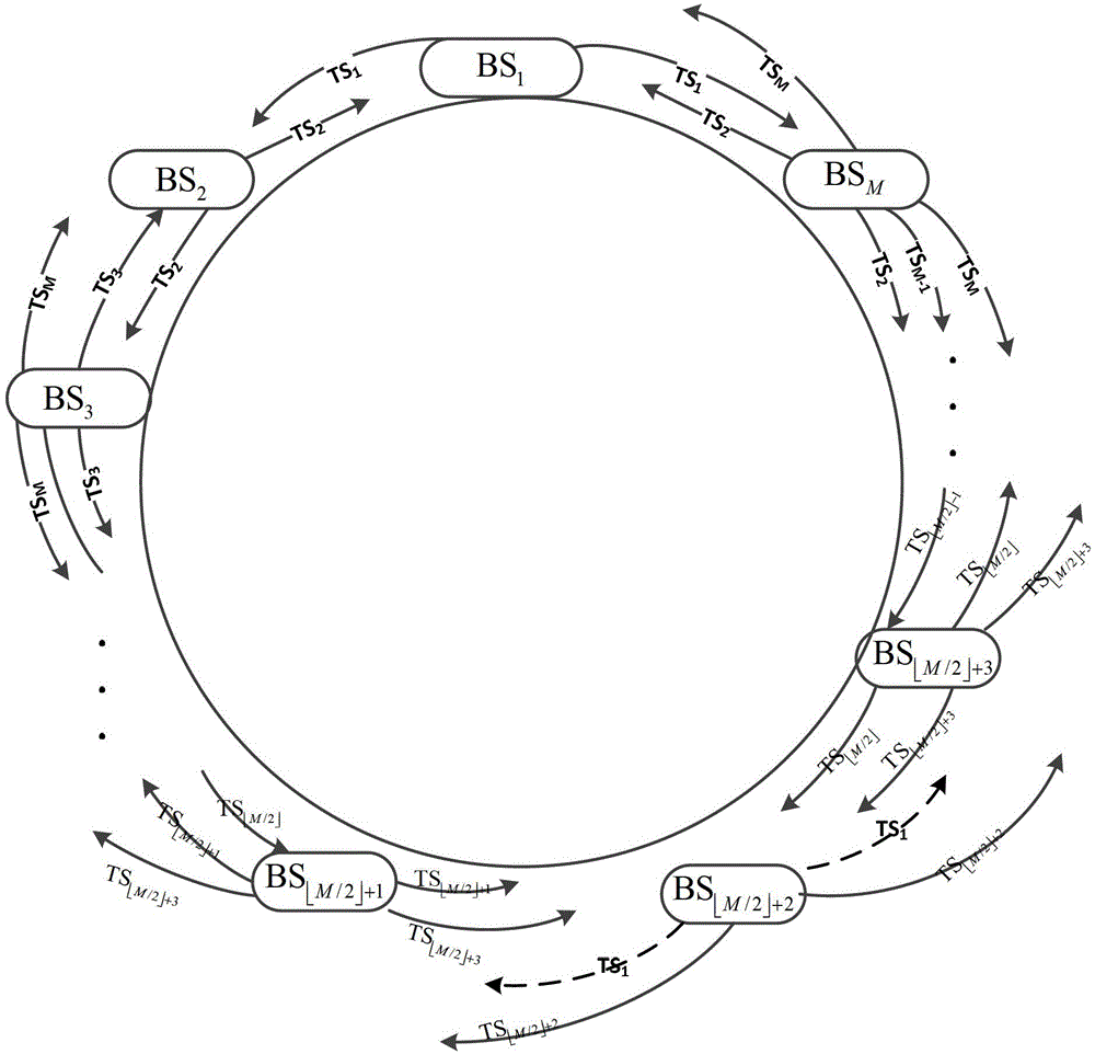
[0038] Embodiment 1: An odd number of base stations at the source end forms a closed-loop structure, and the synchronization signal generating base station is any base station in the closed-loop structure, such as figure 1 shown. Step A specifically includes the following steps: Step A1, in the first time slot, the adjacent base stations on both sides of the intermediate base station respectively estimate the phase offset of the channel with the intermediate base station. figure 1 In the figure, the solid line represents the transmission process of the synchronization signal among the base stations, and the signal transmitted each time is the periodic extension of the previous time slot signal, and the dotted line represents the channel estimation process. At this time, a time slot TS1 is needed for channel estimation ( base station estimate and The channel phase between, estimate and channel phase between), where TS i Indicates the ith time slot, BS i Indicates ...

Embodiment 2

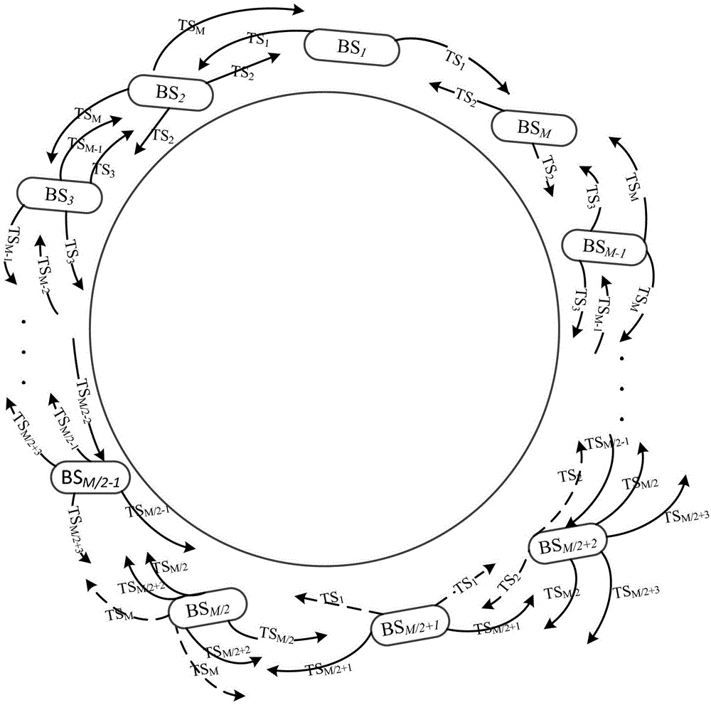
[0039] Embodiment 2: An even number of base stations at the source end forms a closed-loop structure, and the synchronization signal generating base station is any base station in the closed-loop structure, such as figure 2 shown. Step A specifically includes the following steps: Step A2, in the first time slot, the adjacent base stations on both sides of the intermediate base station respectively estimate the phase offset of the channel with the intermediate base station; in the second time slot, the intermediate base station estimates its The phase offset of the channel with the adjacent base station on one side; in the last time slot of the reverse broadcast transfer, the intermediate base station estimates the phase offset of the channel between it and the adjacent base station on the other side. figure 2 In , the solid line represents the transmission process of the synchronization signal between the base stations. The signal transmitted each time is a periodic extensio...

Embodiment 3

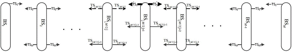
[0040] Embodiment 3: Multiple base stations at the source end can form a linear structure, and the synchronization signal generating base stations are base stations at both ends of the linear structure. At this time, it can be image 3 Odd number of base stations shown, can also be Figure 4 The even number of base stations shown is different from the ring structure in that the synchronization signals generated by the base stations at both ends can be the same or different. Step A specifically includes the following steps: Step A3, in the first time slot, the adjacent base stations on both sides of the intermediate base station respectively estimate the phase offset of the channel with the intermediate base station. for image 3 In the case of , the thin solid line represents the transmission process of the synchronization signal between the base stations. The signal transmitted each time is a periodic extension of the previous time slot signal. The thick solid line represent...


PUM


Abstract

The invention is applicable to the technical field of wireless communication and provides a distributed beam forming system and a carrier synchronization method of transmitting antennas at the source end of the distributed beam forming system. The transmitting antennas at the source end of the distributed beam forming system can realize accurate time slot control, can conduct frequency and phase estimation to received signals and can estimate phase shift information caused by channel time delay. The carrier synchronization method fully utilizes the broadcasting characteristics of wireless links and realizes the accurate synchronization of carrier frequency and phase of the distributed beam forming system through accurate time slot control and channel estimation. Compared with the traditional carrier synchronization method, the carrier synchronization method provided by the invention has the advantages that the synchronization overhead is greatly reduced, the time slot needed for synchronization is decreased to M from 2M-1 (wherein M is the number of source-end base stations) and the effective communication time of the system is increased.

Description

technical field [0001] The invention belongs to the technical field of wireless communication, and in particular relates to a distributed beam forming system and a carrier synchronization method for each transmitting antenna at a source end. Background technique [0002] Distributed beamforming technology is a wireless communication technology that can significantly improve system power efficiency. It forms a virtual antenna array from independent antennas distributed in multiple cells (each antenna has its own crystal oscillator, and only Knowing its own local time), each antenna in the antenna array sends the same signal to the destination base station, where these signals are coherently combined. Due to the scalability and robustness of the virtual antenna array, the distributed beamforming technology can obtain higher directional transmission characteristics than the traditional antenna array, and can obtain a larger signal noise ratio (Signal Noise Ratio) than the singl...

Claims


Application Information

Patent Timeline
Patent Type & Authority Applications(China)
IPC IPC(8): H04W56/00H04B7/04
CPCH04B7/0617H04W56/00
Inventor 谢宁鲍旭王晖林晓辉曾捷
Owner SHENZHEN UNIV
Why Eureka
Try Eureka