
Pneumatic radial aircraft tire

A technology of radial tires and radial tires, applied to the reinforcement layer of pneumatic tires, aircraft tires, tire parts, etc., can solve the problems of damaging the main body of the aircraft, increasing the size of the peeled rubber fragments, etc., and achieve the effect of preventing peeling

Inactive Publication Date: 2013-06-12
BRIDGESTONE CORP
View PDF9 Cites 4 Cited by
  • Summary
  • Abstract
  • Description
  • Claims
  • Application Information

AI Technical Summary

Problems solved by technology

Therefore, if the rubber is peeled at the interface between these cords and the rubber layer located on the outer periphery of the cords, the peeling extends along the cords in the circumferential direction of the tire, thus increasing the size of the fragments of the peeled rubber, and there are fragments such as Risk of damage to the main body of the aircraft due to collision with the aircraft

Method used


Image

  • Pneumatic radial aircraft tire
  • Pneumatic radial aircraft tire
  • Pneumatic radial aircraft tire

Examples


Embodiment )

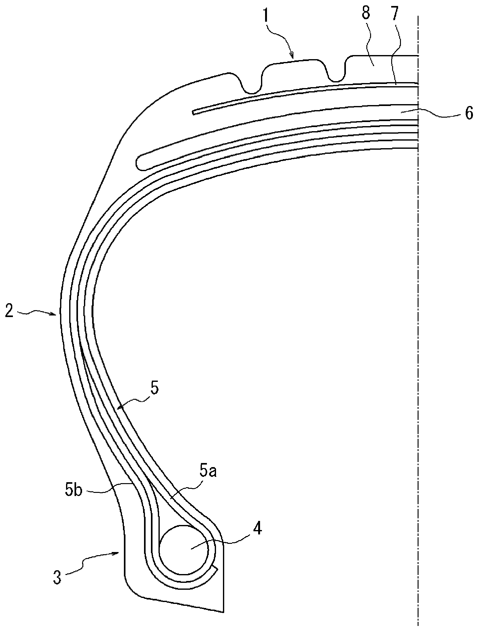
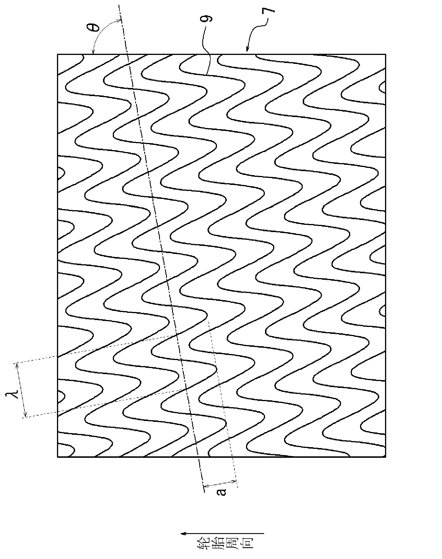
[0048] Note that making a figure 1 and figure 2 The construction shown is a sample tire of dimensions 50 x 20.0R2232PR. As shown in Table 1, the specifications were changed in Example tires 1 to 3 and Comparative example tires 1 to 3, and the peeling resistance of the tread portion and the size of the peeled rubber were measured for each tire.

[0049] Note that the Comparative Example tires did not require structural changes other than the protective layer, and thus were manufactured according to the Example tires.

[0050] Table 1

[0051]

[0052]

[0053] Peel resistance of tread

[0054] Each of Example tires 1 to 3 and Comparative example tires 1 to 3 was mounted to a rim having a size of 50×20OR22 and charged with an internal pressure of 1520 kPa. A central rib width cut was made in each tire from the tread contact patch to the top of the cords in the cover. Next, the start of the test was repeatedly performed under a tire load of 120%, and the number of ru...


PUM


Abstract

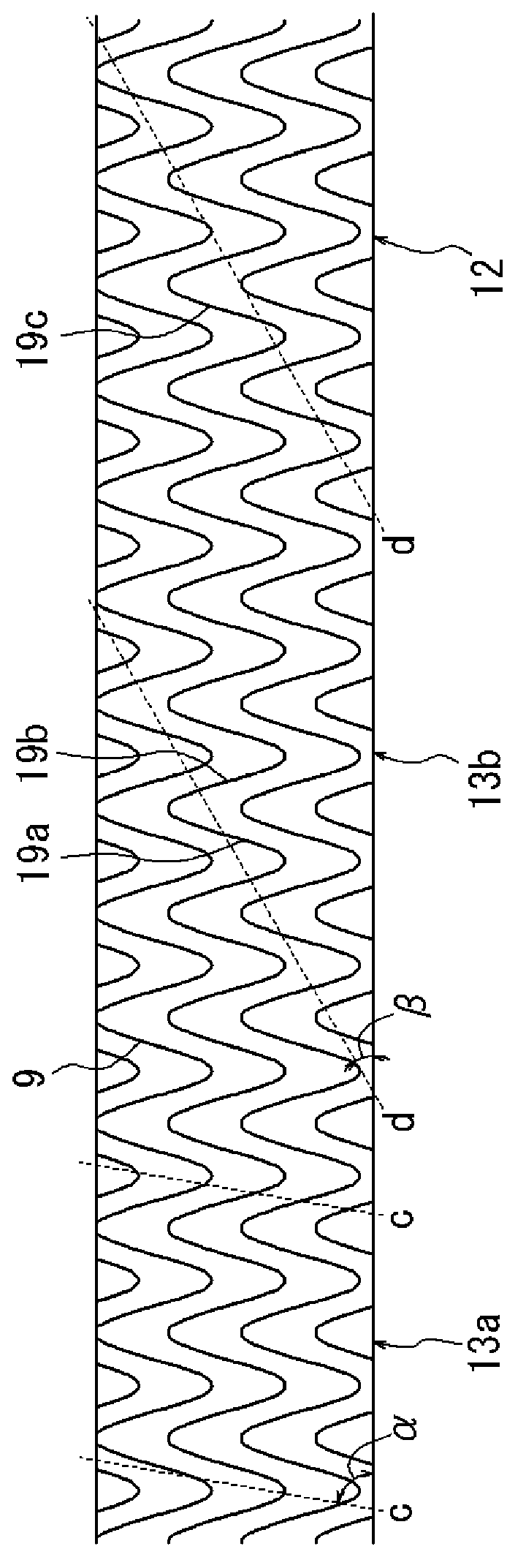
The present invention is characterized by the provision of: a radial carcass that forms the skeletal structure of a tire; a belt (6) disposed radially outwards of a crown region of the radial carcass; and at least one protective layer (7), comprising a plurality of cords, radially outwards of the belt (6). The present invention is further characterized in that: the protective layer (7) is formed by arranging a plurality of cords (9), which trace out sinusoids, in parallel and in phase; and the acute angle (theta) that the circumferential direction of the tire forms with the centerlines of the aforementioned sinusoids, the semi-amplitude (a) of said sinusoids, and the wavelength (lambda) thereof satisfy the relation tan theta > 2pia / lambda > 0.4 (0 DEG < theta < 90 DEG).

Description

technical field [0001] The present invention relates to radial tires for aircraft, and in particular to improvements in pneumatic radial tires for aircraft which reduce the volume of any fragments of tread rubber that are stripped. Background technique [0002] Cuts can occur in the tread when aircraft run over foreign objects that fall on the runway with pneumatic radial tires. If the cut reaches the belt or carcass, the tire may have a puncture, or the tread rubber may be stripped from the tire at the cut. [0003] In order to solve this problem, for example, Patent Document 1 proposes a technique of providing a crown protective layer between a belt layer and a tread. The crown protective layer is formed by a corrugated cord layer and an organic fiber cord layer, wherein the corrugated cord layer is composed of corrugated cords arranged in parallel, and the organic fiber cord layer is located outside the corrugated cord layer in the radial direction of the tire, arranged ...

Claims


Application Information

Patent Timeline
Patent Type & Authority Applications(China)
IPC IPC(8): B60C9/08B60C9/18B60C9/20B60C9/22
CPCB60C2200/02B60C9/18B60C2009/2032Y10T152/10765B60C9/00B60C9/20
Inventor 伊丹大祐
Owner BRIDGESTONE CORP
Learn More