Plasma-coated sealing elements
A technology of sealing components and plasma, which is applied in the direction of engine sealing, coating, engine components, etc., can solve the problems of sealing body wear, dynamic seals without lubricant research, etc.
- Summary
- Abstract
- Description
- Claims
- Application Information
AI Technical Summary
Problems solved by technology
Method used
Image
Examples
example 10
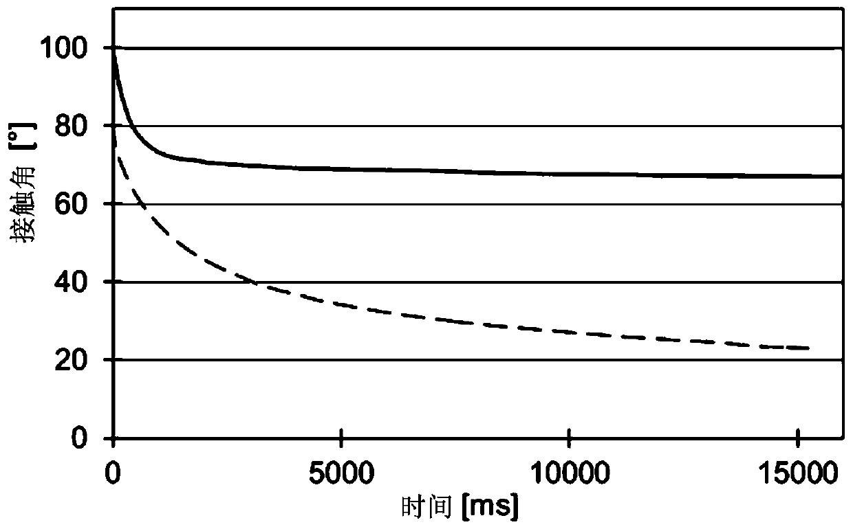
[0103] Example 10: Determination of Surface Energy and Contact Angle
[0104] In order to determine the surface energy, contact angle measurements are carried out at the placed droplet. Here, the treatment was carried out analogously to the DIN 55660-2 standard of December 2011, except for the test climate. Measurements were performed at a temperature of 23-26°C. Water and diiodomethane were used as measuring liquids. According to the Owens-Wendt method, the surface energy was calculated based on the contact angles derived from the measurements. Here, the total surface energy is composed of polar and dispersed fractions.
[0105] Contact angle measurements were performed 1 day, 7 days and 30 days after the coating process. All surfaces were cleaned with ethanol before measurement. Since the matrix material is a multicomponent system, its individual components partially tend to migrate, and the measured value of the contact angle fluctuates around a maximum of 10° depend...
example 11
[0110] Example 11: Tribological properties without lubricant
[0111] To characterize the friction reduction of the coatings, coated and uncoated samples were moved on stainless steel plates (Ra = 1.062 μm) and subjected to the necessary force. For this, three specimens are placed into special holders which allow for each specimen a distance of approximately 6.5 mm from the counterpart 2 contact surface. The holder is laid down with the sample onto the counterpart and a mass of 1 kg is weighed out. The counterpart is then moved at a speed of 150mm / min and the force required to hold the holder in place is measured. The measurements were carried out three times sequentially and the average values are summarized in Table 5. The results showed that the coating significantly improved the friction properties of the elastomer.
[0112] from example base Force [N] 1(V) FKM I 12.4 2 FKM I with layer 2 2.3 5(V) EPDM I 10.9 6 EPDM with lay...
example 12
[0118] Example 12: Tribological properties with lubricants
[0119] In order to characterize the properties of the lubricated sealing system, comparative experiments were carried out on a disc test rig (for this see also M. Sommer, W. Haas: "A new approach on grease tribology in sealing technology: Influence of the thickener particles (sealing A New Approach to Grease Tribology in Technology: The Effect of Thickener Particles), Tribology International, Vol. 103, November 2016, pp. 574-583). For this, a test piece consisting of FKM I was used, and a comparative test was carried out uncoated and coated with layer 2 (according to examples 1 and 2). A polyalkylene glycol oil of ISO viscosity class 460 (Klübersynth UH1 6-460) was used as lubricant. Temper the test device to 60°C. image 3 Results are shown with coated FKM (circles) and uncoated FKM (squares). A significant friction reduction due to the coating was also clearly observed in the lubricated sealing system. The ef...
PUM
| Property | Measurement | Unit |
|---|---|---|
| Hardness | aaaaa | aaaaa |
Abstract
Description
Claims
Application Information
 - R&D
- Intellectual Property
- Life Sciences
- Materials
- Tech Scout
- Unparalleled Data Quality
- Higher Quality Content
- 60% Fewer Hallucinations
Browse by: Latest US Patents, China's latest patents, Technical Efficacy Thesaurus, Application Domain, Technology Topic, Popular Technical Reports.
© 2025 PatSnap. All rights reserved.Legal|Privacy policy|Modern Slavery Act Transparency Statement|Sitemap|About US| Contact US: help@patsnap.com


