

Propeller hub fairing skin machining method
A processing method and fairing technology, which is applied in the field of aviation manufacturing, can solve problems such as overweight parts, achieve the effects of improving fatigue strength and surface hardness, making grains thinner, and meeting design requirements
Inactive Publication Date: 2013-06-19
SHAANXI AIRCRAFT CORPORATION
View PDF3 Cites 8 Cited by
- Summary
- Abstract
- Description
- Claims
- Application Information
AI Technical Summary
Problems solved by technology
[0003] Purpose of the invention: To provide a method for processing the skin of the hub fairing, which adopts thickened sheet material to be powerfully spun into parts with equal thickness curves, and solves the problem of overweight parts
Method used
View moreImage
Smart ImageViewing Examples

Examples
example
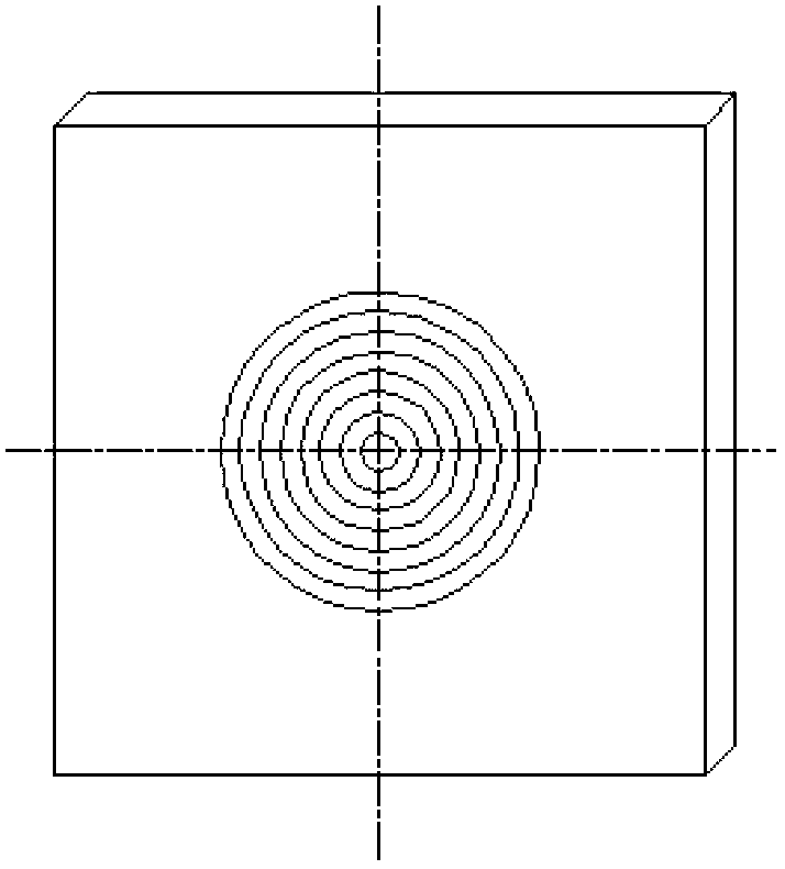
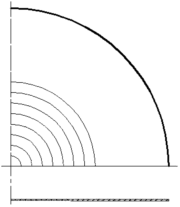
[0022] Example: Taking the hub spinner skin of a certain type of aircraft as an example, the milling thickness value is shown in the table below, and the section shape is shown in Figure 5 .
[0023] distance to vertex
Login to View More PUM
 Abstract
The invention belongs to the field of aviation manufacturing and particularly relates to a propeller hub fairing skin machining method. The propeller hub fairing skin machining method comprises the steps of blanking, milling to flat plate woolen materials, the steps of forming variable thickness materials, the steps of forming variable thickness revolving body materials, powerspinning to the woolen materials and the steps of forming parts of revolving body shapes. The propeller hub fairing skin machining method overcomes the wrinkling problem caused by ordinary flow forming and further overcomes the problems of raw materials waste and low part fatigue strength brought by part appearance obtained by a method of mechanical machining. Due to the fact that a technology method of variable thickness powerspinning curve parts is adopted, the defect that uniform thickness plate materials are turned into different thickness curve parts in a powerspinning mode is overcome. In addition, in the process of attenuation flow forming, pressure stress on the surface of the parts is large, and the parts obtain large surface hardness. The mechanical performance of the parts is improved, and the fatigue strength and the surface hardness of the parts are improved. The overweight problem of powerspinning parts commonly existing in a sheet metal industry is solved.
Description
technical field [0001] The invention belongs to the field of aviation manufacturing, and in particular relates to a skin processing method of a hub fairing. Background technique [0002] The manufacturing process of aircraft engine nacelle involves the special spinning process of propeller hub parts. This type of parts has high external precision, smooth and streamlined surface, and strict dimensional accuracy (thickness) and weight requirements. In actual production, it was found that the batch of parts was overweight by 9.3% to 14.5% during the weighing inspection of the powerful spinning hub spinner skin parts. After weighing and measuring the thickness of the batch-produced parts one by one, the overweight reaches 153-239g. The long-standing problem of overweight of such parts has seriously affected the quality of the aircraft. In the existing ordinary spinning technology, during the spinning forming process, there is always tangential compressive stress on the edge of...
Claims
Login to View More Application Information
Patent Timeline
 IPC IPC(8): B23P15/00
Inventor佟晓冬阮义青王劲松代文宏王宏生
OwnerSHAANXI AIRCRAFT CORPORATION