Hot-stamping device of optical waveguide

A hot imprinting and optical waveguide technology, which is applied in the field of hot imprinting devices, can solve the problems of uncontrollable cooling and pressure of hot imprinting, uncontrollable hot imprinting temperature, uneven heating of samples, etc., so as to improve the quality of hot imprinting. , Solve the effect of uneven heating and smooth demoulding

Active Publication Date: 2013-06-19
NINGBO UNIV
View PDF4 Cites 6 Cited by
  • Summary
  • Abstract
  • Description
  • Claims
  • Application Information

AI Technical Summary

Problems solved by technology

The existing thermal embossing device mainly has the following disadvantages: the heating method of heat conduction makes the sample heated unevenly, and the temperature of the thermal embossing is uncontrollable; the cooling and pressure of the thermal embossing are uncontrollable, and it is difficult to achieve accurate imprinting. It is difficult to release the sample after completion

Method used


Image

  • Hot-stamping device of optical waveguide

Examples


Embodiment Construction

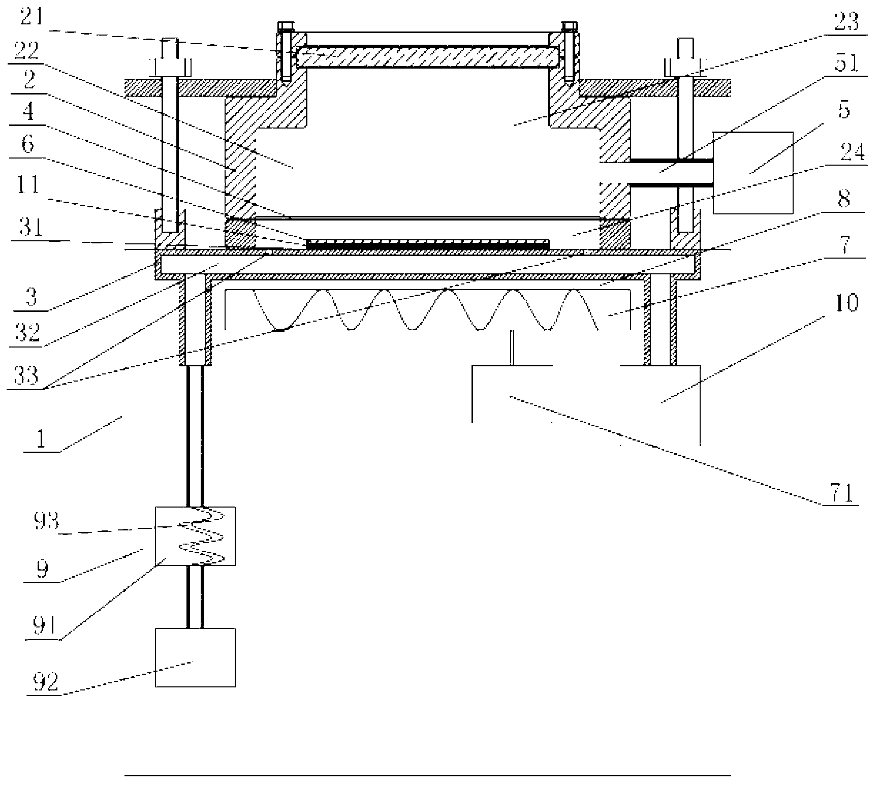
[0012] The present invention will be further described in detail below in conjunction with the accompanying drawings and embodiments.

[0013] As shown in the figure, a thermal embossing device for an optical waveguide includes a base 1, a thermal embossing cavity 2 with an open bottom, and a sample stage 3 arranged on the base 1; the top of the thermal embossing cavity 2 is provided with a cover plate 21, the hot embossing chamber 2 is fixed above the sample stage 3, and the hot embossing chamber 2 is provided with a working chamber 22, and the working chamber 22 is provided with a film layer 4 capable of high temperature resistance, and the film layer 4 will work Chamber 22 is divided into pressure chamber 23 and vacuum chamber 24, and pressure chamber 23 is positioned at the top of vacuum chamber 24, and pressure chamber 23 is connected with pneumatic pressure booster 5 through gas pipeline 51; 6 is located in the vacuum chamber 24; a resistance wire heating device 7 with a...


PUM


Abstract

The invention discloses a hot-stamping device of optical waveguide. The hot-stamping device is characterized in that a cover plate is arranged at the top of a hot-stamping cavity body; the hot-stamping cavity body is fixedly arranged above a sample platform and is internally provided with a working cavity which is internally provided with a high-temperature-resistant film layer; the film layer divides the working cavity into a pressure cavity and a vacuum cavity; the pressure cavity is positioned above the vacuum cavity and is connected with a pneumatic boosting device by a gas pipeline; a mold is placed on a platform surface of the sample platform and is positioned in the vacuum cavity; a heating device with a temperature control system is arranged below the sample platform; a gap is reserved between the sample platform and the heating device; the sample platform is internally provided with a heat buffering cavity; the vacuum cavity is communicated with the heat buffering cavity; and one side of the heat buffering cavity is connected with a cooling device, and the other side of the heat buffering cavity is connected with a vacuumizing device. The hot-stamping device disclosed by the invention has the advantages that the temperature, cooling and pressure of hot stamping can be controlled, the hot-stamping sample is heated uniformly, the demolding is smooth after hot stamping, and the hot-stamping quality of the optical waveguide can be greatly improved.

Description

technical field [0001] The invention relates to a thermal embossing device, in particular to a thermal embossing device for an optical waveguide. Background technique [0002] Optical waveguides are components of integrated optics. At present, the relatively mature waveguide preparation methods are mostly based on photolithography technology, and its disadvantages are cumbersome process, expensive equipment, long production cycle, high cost, and difficult process control. Therefore, people have been exploring a simple, low-cost, fast and controllable waveguide preparation method. [0003] Hot embossing technology is a low-cost waveguide preparation technology, and its principle is to realize the transfer of graphics through a special mold with a concave-convex structure. The existing hot embossing device generally puts the sample directly on the heating device, heats the sample to a certain temperature above its softening temperature through heat conduction heating, and th...

Claims


Application Information

Patent Timeline
Patent Type & Authority Applications(China)
IPC IPC(8): B29C59/02B29L11/00
Inventor 沈祥宗双飞聂秋华徐铁峰戴世勋李军张培全付晶
Owner NINGBO UNIV
Why Eureka
Try Eureka