Magnetic valve

A solenoid valve and solenoid coil technology, applied in the field of solenoid valves, can solve problems such as difficult control, and achieve the effects of easy assembly, increased size, and reduced cost

Active Publication Date: 2013-06-19
SAGINOMIYA SEISAKUSHO INC
View PDF14 Cites 5 Cited by
  • Summary
  • Abstract
  • Description
  • Claims
  • Application Information

AI Technical Summary

Problems solved by technology

[0042] However, in such a coil spring 400 with unequal pitches, the spring constants of the coil portions 402, 404 at both ends and the central coil portion 406 change. image 3 The relation...

Method used


Image

  • Magnetic valve
  • Magnetic valve
  • Magnetic valve

Examples


Embodiment 1)

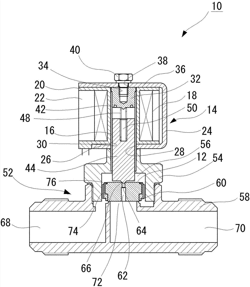
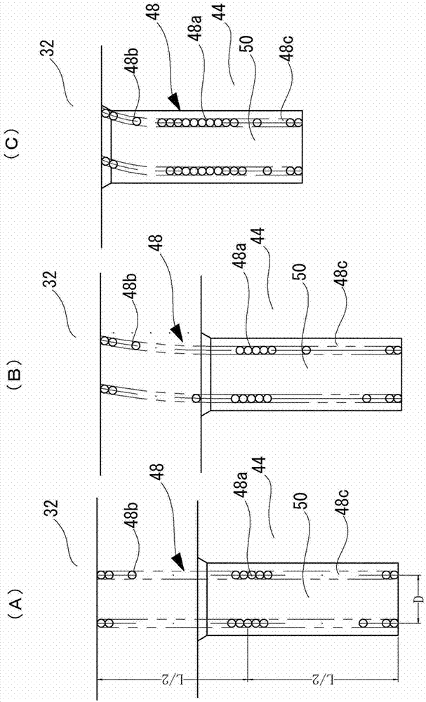
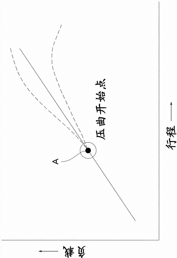
[0090] figure 1 is a schematic longitudinal sectional view of the solenoid valve of the present invention, figure 2 yes figure 1 Partial enlarged cross-sectional view of the solenoid valve, figure 2 (A) is a partially enlarged cross-sectional view showing a state in which the plunger is separated from the attractor and buckling does not occur in a state where the energization of the electromagnetic coil is cut off, figure 2 (B) is a partially enlarged cross-sectional view showing a state in which buckling occurs in a state where energization of the electromagnetic coil is started, figure 2 (C) is a partially enlarged cross-sectional view showing a state in which the plunger is in contact with the attractor when the electromagnetic coil is energized, image 3 It is a graph showing the relationship between stroke and load.

[0091] exist figure 1 In , reference numeral 10 generally indicates the solenoid valve of the present invention.

[0092] The solenoid valve 10...

Embodiment 2)

[0137] Figure 5 is a partially enlarged cross-sectional view of a solenoid valve 10 showing another embodiment of the present invention, Figure 5 (A) is a partially enlarged cross-sectional view showing a state in which the plunger is separated from the attractor and buckled in a state where the energization to the electromagnetic coil is cut off, Figure 5 (B) is a partially enlarged cross-sectional view showing a state where buckling occurs when the electromagnetic coil is started to be energized, Figure 5 (C) is a partially enlarged cross-sectional view showing a state in which the plunger is in contact with the attractor when the electromagnetic coil is energized.

[0138] The configuration of the solenoid valve 10 of this embodiment is basically the same as that of the solenoid valve 10 shown in the first embodiment, and the same components are assigned the same reference numerals, and detailed description thereof will be omitted.

[0139] In the solenoid valve 10 of...

Embodiment 3)

[0143] Image 6 is a partially enlarged cross-sectional view of a solenoid valve 10 showing another embodiment of the present invention, Image 6 (A) is a partially enlarged cross-sectional view showing a state in which the plunger is separated from the attractor and buckling does not occur in a state where the energization of the electromagnetic coil is cut off, Image 6 (B) is a partially enlarged cross-sectional view showing a state in which the plunger is in contact with the attractor when the electromagnetic coil is energized.

[0144] The configuration of the solenoid valve 10 of this embodiment is basically the same as that of the solenoid valve 10 shown in Embodiment 1, and the same components are assigned the same reference numerals, and detailed description thereof will be omitted.

[0145] In the solenoid valve 10 of this embodiment, as Image 6 As shown in (A), the attractor 32 has a substantially conical fitting protrusion 32 a that protrudes toward the plunger ...


PUM


Abstract

The invention provides an magnetic valve provided with a spiral spring so as to reliably move; the spiral spring can hardly generate curve, so offset amount caused by curve is reduced, the spring is prevented from extending out a spring mounting hole, and the spring will not be clamped between an attractor and a plunger when being electrified. The magnetic valve comprises the following structures: a plunger (44) using charging of a magnetic coil (18) to move and enabling a valve body (12) to move; the attractor (32) configured in a mode opposite to the plunger (44); the spiral spring (48) arranged between the spring mounting hole (50) formed on one side of the attractor (32) of the plunger (44) and the attractor (32), and applying force to the plunger (44) in a valve seat (66) direction; and a middle part of the spiral spring (48) is provided with a dense winding portion (48a) in which adjacent coils are winded in a mutually attached state.

Description

technical field [0001] The present invention relates to a solenoid valve, and more particularly to a solenoid valve provided with a coil spring installed between a spring mounting hole formed on an attractor side of a plunger and the attractor, and biasing the plunger toward a valve seat. Background technique [0002] In the past, for example, pilot solenoid valves equipped with pilot valves such as Figure 9 constructed as shown. [0003] That is, if Figure 9 As shown, the solenoid valve 100 includes a control unit 104 having a piston 102 as a main valve. In addition, the control unit 104 of the electromagnetic valve 100 includes an electromagnetic coil 108 through which the drive unit 106 is inserted. [0004] Furthermore, the electromagnetic coil 108 and the bobbin 110 around which the coiled wire is wound are molded with a molding resin 112 so as to surround the bobbin 110 . Furthermore, the electromagnetic coil 108 is installed inside the magnetic frame 114 and fixed...

Claims


Application Information

Patent Timeline
IPC IPC(8): F16K31/06
CPCF16K27/029F16K31/0658F16K31/10F16K51/00
Inventor 上野知之铃木龙介佐藤宪丸山纪郎稻村大作吉野谷宽人
Owner SAGINOMIYA SEISAKUSHO INC
Why Eureka
Try Eureka