Water level detecting device
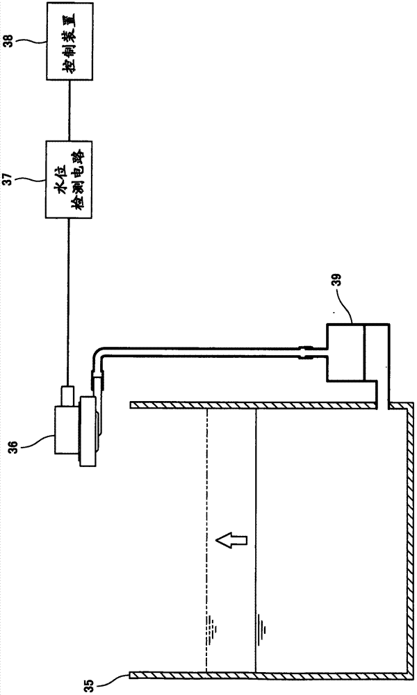
A technology of water level detection and box, which is applied in the direction of measuring device, measuring capacity, liquid/fluid solid measurement, etc. It can solve the problems of water level detection accuracy drop, pedestal 31 sloshing, inductance coefficient not being a fixed value, etc.
- Summary
- Abstract
- Description
- Claims
- Application Information
AI Technical Summary
Problems solved by technology
Method used
Image

Examples
no. 1 Embodiment approach
[0027] First, use Figure 1 ~ Figure 3 The configuration of the water level detection device in the first embodiment will be described.
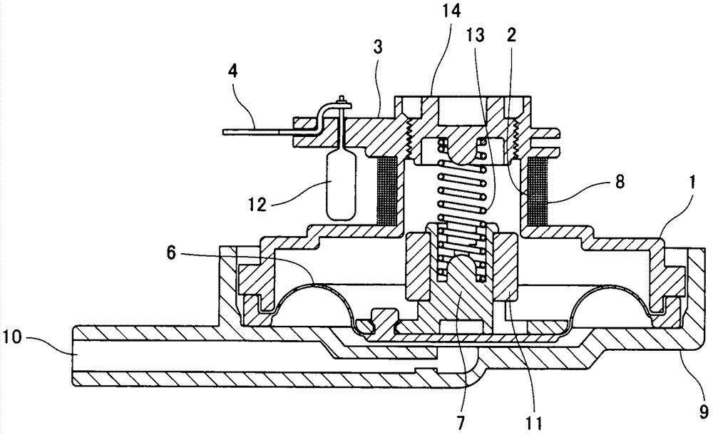
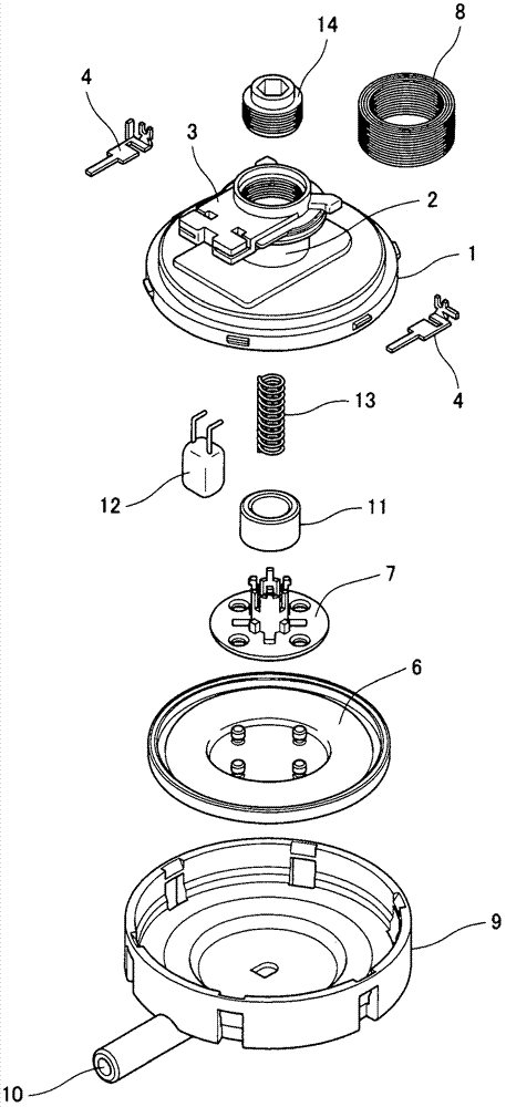
[0028] figure 2 is a cross-sectional view showing the structure of the water level detection device in the first embodiment, image 3 It is an exploded perspective view showing the structure of the water level detection device in the first embodiment.
[0029] Such as figure 2 , image 3 As shown, a diaphragm plate 6 is provided in a lower case 9 having an inlet 10, and the diaphragm plate 6 is connected to an iron core 11 made of iron oxide or the like through a connecting plate 7. The central portion of the diaphragm plate 6 is recessed from the peripheral portion under normal pressure, and a predetermined space is formed between the lower case 9 and the diaphragm plate 6 . This space is connected to the inlet 10 . The upper box body 30 is installed on the lower box body 9, and the upper box body 30 and the lower box body 9 wrap th...
no. 2 Embodiment approach
[0036] Next, use Figure 4A , Figure 4B The configuration of the water level detection device in the second embodiment will be described.
[0037] Figure 4A , Figure 4B It is a figure which shows the structure of the water level detection apparatus in 2nd Embodiment, Figure 4A It is an exploded perspective view showing the main part, Figure 4B is a cross-sectional view.
[0038] The water level detection device of the second embodiment is characterized in that holes are provided in the upper case of the water level detection device of the first embodiment.
[0039] Such as Figure 4A , Figure 4B As shown, a hole 15 is formed in a region of the upper case 1 opposite to the position where the capacitor 12 is mounted on the terminal block 3 . The size of the hole 15 is such that the capacitor 12 can pass through. By providing such a hole 15, when the height of the coil installation part 2, which is the distance between the terminal block 3 and the upper case 1, is ...
PUM
 Abstract
Description
Claims
Application Information
 - R&D
- Intellectual Property
- Life Sciences
- Materials
- Tech Scout
- Unparalleled Data Quality
- Higher Quality Content
- 60% Fewer Hallucinations
Browse by: Latest US Patents, China's latest patents, Technical Efficacy Thesaurus, Application Domain, Technology Topic, Popular Technical Reports.
© 2025 PatSnap. All rights reserved.Legal|Privacy policy|Modern Slavery Act Transparency Statement|Sitemap|About US| Contact US: help@patsnap.com