Zero shutter thermal infrared imager based on voice operated exchange (VOX) detector and use method thereof

A technology of infrared thermal imager and detector, applied in the field of infrared imaging, can solve the problems of large residual error, unfavorable system real-time processing, affecting the performance and application of thermal imager, and achieve the effect of eliminating residual error

Inactive Publication Date: 2013-06-19
北京红源盛达光电技术有限公司
View PDF6 Cites 15 Cited by
  • Summary
  • Abstract
  • Description
  • Claims
  • Application Information

AI Technical Summary

Problems solved by technology

However, although this generation of thermal imaging general-purpose components has been widely used, it has been found to have serious shortcomings: high cost, difficult maintenance and logistics support (refrigeration), and poor reliability
[0007] The shortcomings of these correction methods are residual errors, and the residual errors are related to the temperature of the detector and the shutter. The residual errors appear as a layer of noise on the video, which affects the performance and application of the thermal imager.
[0008] Analyze the two types of non-uniformity correction methods in the past, calibration-based correction...

Method used


Image

  • Zero shutter thermal infrared imager based on voice operated exchange (VOX) detector and use method thereof
  • Zero shutter thermal infrared imager based on voice operated exchange (VOX) detector and use method thereof
  • Zero shutter thermal infrared imager based on voice operated exchange (VOX) detector and use method thereof

Examples


Embodiment 1

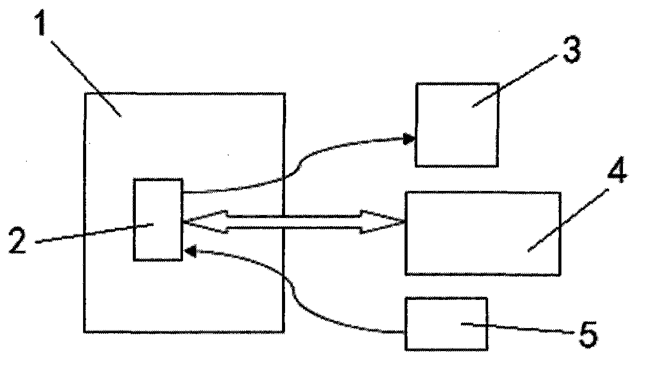
[0111] Such as figure 2 As shown, the VOx detector-based shutterless infrared thermal imaging camera according to Embodiment 1 of the present invention includes a high and low temperature box 1, and a movement 2 is provided in the high and low temperature box 1, and the movement 2 is respectively connected to There are monitor 3 , computer 4 and power supply 5 .

[0112] Adopt embodiment 1 (as figure 2 ) said thermal imaging camera realizes the acquisition of no shutter sample coefficient:

[0113]Write the program for the thermal imager, connect the communication cable, then put the infrared thermal imager in the high and low temperature box, set the high and low temperature box to the lowest temperature TL ℃, keep warm for 2 hours to fully cool the thermal imager, and give the thermal image Power on the camera, send a control command for shutter coefficient to the thermal imager through the communication cable, and the thermal imager starts to detect the temperature. Whe...

Embodiment 2

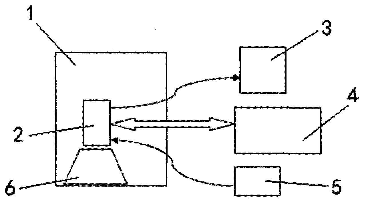
[0122] Such as image 3 As shown, the VOx detector-based shutterless infrared thermal imager described in Embodiment 2 of the present invention includes a high and low temperature box 1, and the high and low temperature box 1 is provided with a movement 2 and a lens 6, and the movement 2 are respectively connected with a monitor 3, a computer 4 and a power supply 5.

[0123] Adopt embodiment 2 (as image 3 ) The infrared thermal imaging camera realizes the collection of sample coefficients without a shutter: the process is the same as in Embodiment 1.


PUM


Abstract

The invention relates to a zero shutter thermal infrared imager based on a voice operated exchange (VOX) detector. The zero shutter thermal infrared imager based on the VOX detector comprises a high-low temperature chamber and a machine core, wherein a monitor, a computer and a power source are respectively connected with the machine core. The use method of the thermal infrared imager includes the following steps: collecting original images; forecasting a background; revising a point 2 and a point 1; and performing image enhancement display processing. Compared with a usual shutter revision method, the zero shutter thermal infrared imager based on the VOX detector and the use method thereof can effectively reduce the size and the power consumption of an infrared machine core, are unlike a conventional method in which a shutter needs to be used to obtain uniform images at every time of revision, and use the original images as background images to revise, and therefore system design is simplified greatly, the size and the power consumption are reduced, and simultaneously due to zero shutter design, the problems of uneven images caused by heat emitting of the shutter and the like are avoided.

Description

technical field [0001] The invention belongs to the technical field of infrared imaging, and in particular relates to a shutterless infrared thermal imager based on a VOx detector and a use method thereof. Background technique [0002] The history of uncooled thermal imaging. Camera tubes made of infrared pyroelectric materials appeared in the early days, and thermal televisions were made. However, the sensitivity is too low, and the image smear phenomenon is serious, so it has not been widely used. It was used in industrial thermal imaging in the 1980s and 1990s. However, although this generation of thermal imaging general-purpose components has been widely used, it has been found to have serious shortcomings: high cost, difficult maintenance and logistics support (refrigeration), and poor reliability. Therefore, the national militaries of the United Kingdom and the United States have formulated plans to develop uncooled thermal imaging, with the aim of developing therma...

Claims


Application Information

Patent Timeline
IPC IPC(8): G01J5/20
Inventor 孙占元
Owner 北京红源盛达光电技术有限公司
Why Eureka
Try Eureka