Optical connector and method of assembling optical connector

Active Publication Date: 2011-12-01
THE FUJIKURA CABLE WORKS LTD
View PDF3 Cites 0 Cited by
  • Summary
  • Abstract
  • Description
  • Claims
  • Application Information

AI Technical Summary

Benefits of technology

[0017]Since the optical connector of the present invention fixes tension-resisting members by the screwing on of a fixing cap, it can easily and rigidly fix tension-resisting members to a housing.
[0018]Also, since the tension-resisting members are fixed at positions separated in the circumferential dire

Problems solved by technology

However, in the aforementioned optical connector, since a specialized tool is required for as

Method used


Image

  • Optical connector and method of assembling optical connector
  • Optical connector and method of assembling optical connector
  • Optical connector and method of assembling optical connector

Examples


Embodiment Construction

[0027]Hereinbelow, an embodiment of the present invention shall be described with reference to the drawings.

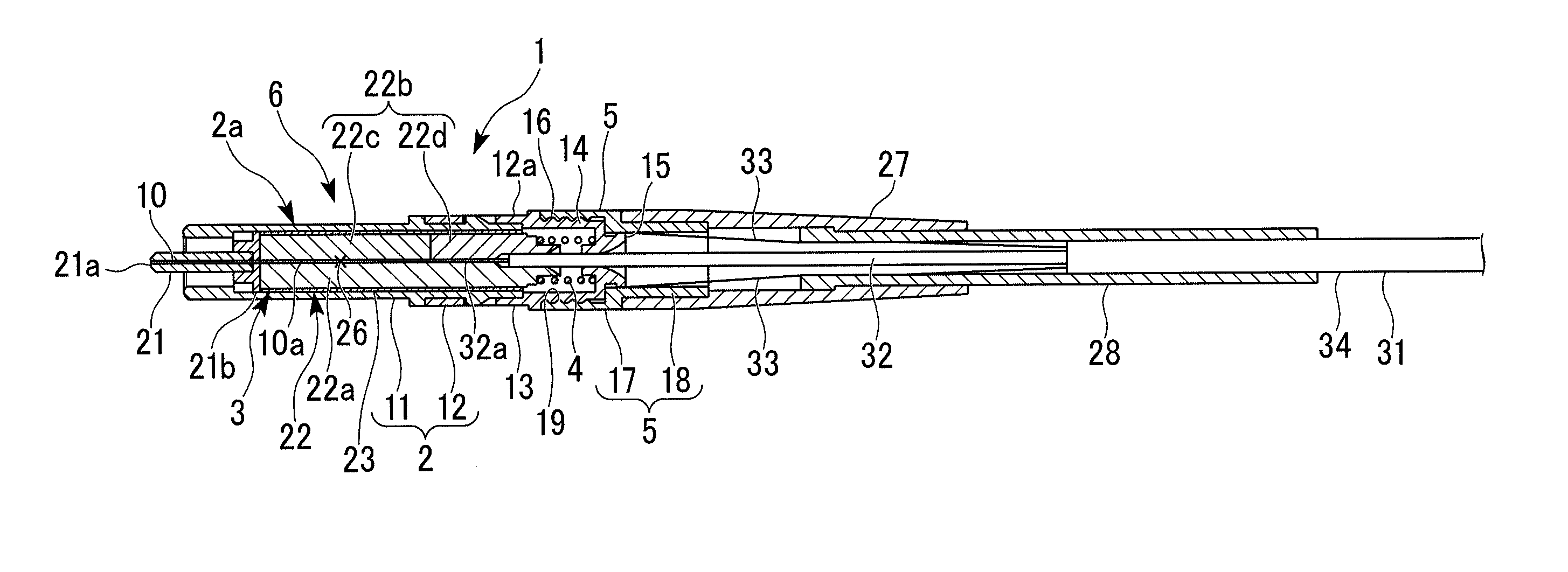
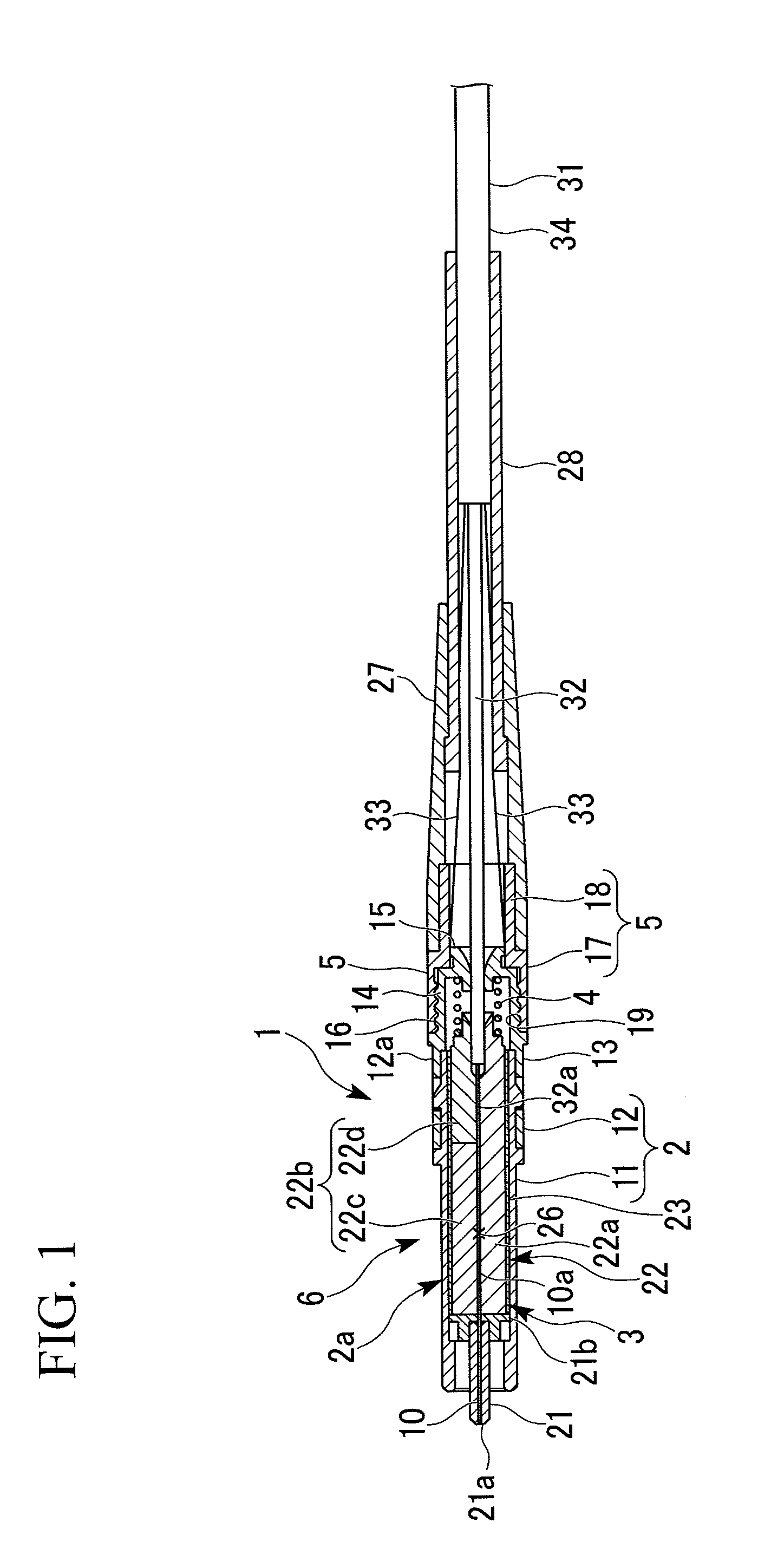
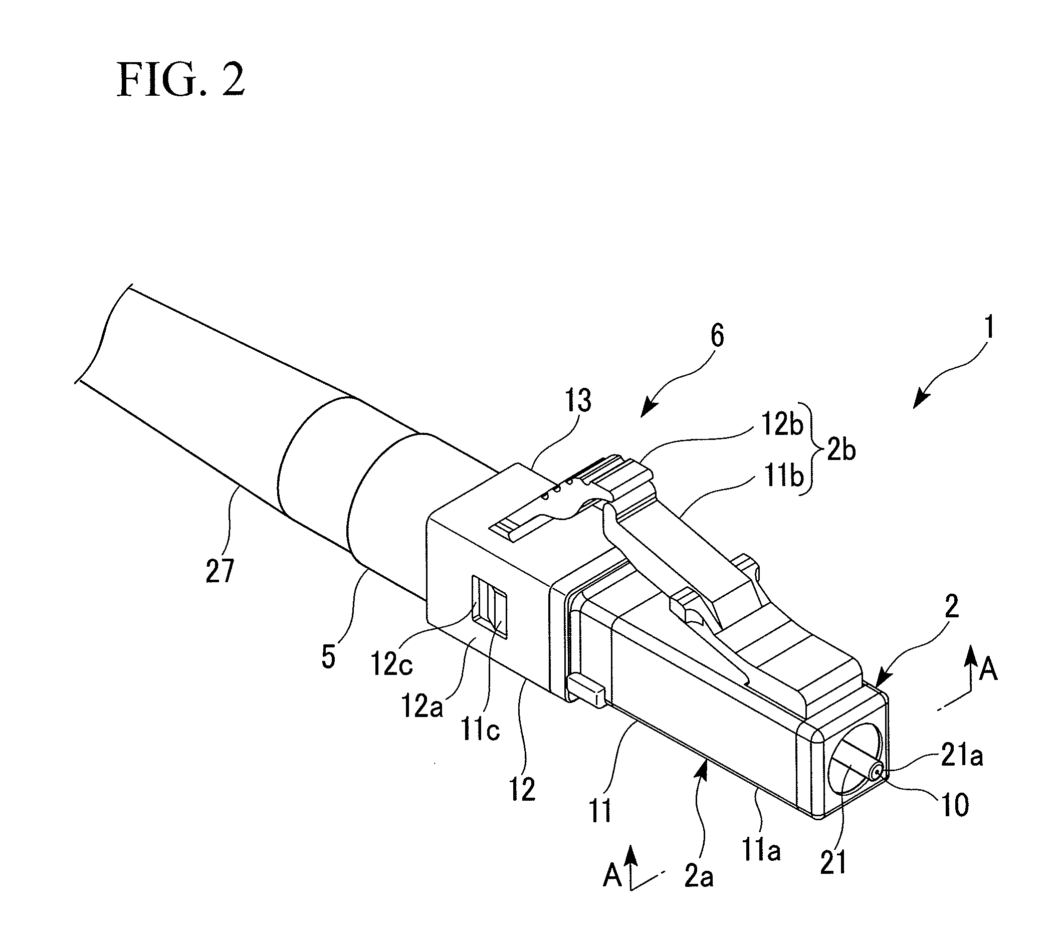
[0028]FIG. 1 is a cross-sectional view that shows an optical connector 1 according to an embodiment of the present invention. FIG. 1 is a cross-sectional view along line A-A in the direction of the arrow in FIG. 2. FIG. 2 is a perspective view that shows the external appearance of the optical connector 1. FIG. 3 is an exploded perspective view of the optical connector 1. FIG. 4 is a perspective view that shows a stop ring body 12a. FIG. 5 is a perspective view that shows a fixing cap 5 that is used in the optical connector 1. FIG. 6 is a side view that schematically shows a stop ring 12, a fixing cap 5, and a boot 27 of the optical connector 1. FIG. 7 is a perspective view that schematically shows the state of tension-resisting members 33 fixed to the optical connector 1.

[0029]As shown in FIG. 1 and FIG. 2, an optical connector 1 is assembled at the terminal of an optical fibe...


PUM

PropertyMeasurementUnit
Shapeaaaaaaaaaa
Tensionaaaaaaaaaa

Abstract

An optical connector that is assembled at the terminal of an optical fiber cable that integrates an optical fiber and a tension-resisting member extending in the longitudinal direction of the optical fiber, the optical connector including: a connector body having a stationary portion at the rear end thereof, the stationary portion having a threaded portion formed on the outer periphery surface, and a fixing cap that is screwed onto the threaded portion of the stationary portion, wherein the fixing cap fixes the tension-resisting member that has been drawn out from the optical fiber cable terminal by sandwiching the tension-resisting member between the fixing cap and the connector body when the fixing cap is screwed onto the stationary portion.

Description

CROSS REFERENCE TO RELATED APPLICATIONS[0001]This application is a continuation application based on a PCT Patent Application No. PCT / JP2009 / 007172, filed Dec. 24, 2009, whose priority is claimed on Japanese Patent Application No. 2009-031875 filed Feb. 13, 2009, the entire content of which are hereby incorporated by reference.BACKGROUND OF THE INVENTION[0002]1. Field of the Invention[0003]The present invention relates to an optical connector, and in particular to an on-site assembly type optical connector that can be assembled without special tools at a workplace, and to a method of assembling the optical connector.[0004]2. Description of the Related Art[0005]As an optical connector that is assembled at the distal end of an optical fiber cable (for example, an optical cord) that has tension resisting fibers, there is one that has a structure that anchors the tension resisting fibers.[0006]As such an anchor structure, there is for example a structure that crimp-fixes the tension res...

Claims


Application Information

Patent Timeline
IPC IPC(8): G02B6/36B23P11/00
CPCY10T29/49947G02B6/3887G02B6/3888
Inventor SAITO, DAIGOTAKIZAWA, KAZUHIROTAN, SERIN KHEE YEN
Owner THE FUJIKURA CABLE WORKS LTD
Why Eureka
Try Eureka