Ground fault diagnosis method for direct current system

A DC system and ground fault technology, applied in the field of power grid safety management, can solve problems such as device malfunction, affecting the safe operation of the power grid, and large sum of capacitance to ground, etc., to achieve reliable basis and guidance, practical and reliable methods, and simple methods. Effect

Inactive Publication Date: 2013-06-19
NANYANG POWER SUPPLY COMPANY OF STATE GRID HENAN ELECTRIC POWER
View PDF1 Cites 3 Cited by
  • Summary
  • Abstract
  • Description
  • Claims
  • Application Information

AI Technical Summary

Problems solved by technology

But in fact, in large substations, due to the increase of the capacitance of the equipment to the ground, one point grounding will also cause the relay protection to malfunction. Connected in parallel, the sum of the ground capacitance of each branch is relatively large, and the resonance is caused by the formation of resonance under specific interference
The existence of this phenomenon can greatly affect the operation of relay elements and switching elements, and cause malfunctions
When the interference signal and insulation parameters in the DC system are in a certain frequency band, the DC system in operation can resonate, resulting in malfunction of the device and seriously affecting the safe operation of the power grid.

Method used


Image

  • Ground fault diagnosis method for direct current system
  • Ground fault diagnosis method for direct current system
  • Ground fault diagnosis method for direct current system

Examples


Embodiment Construction

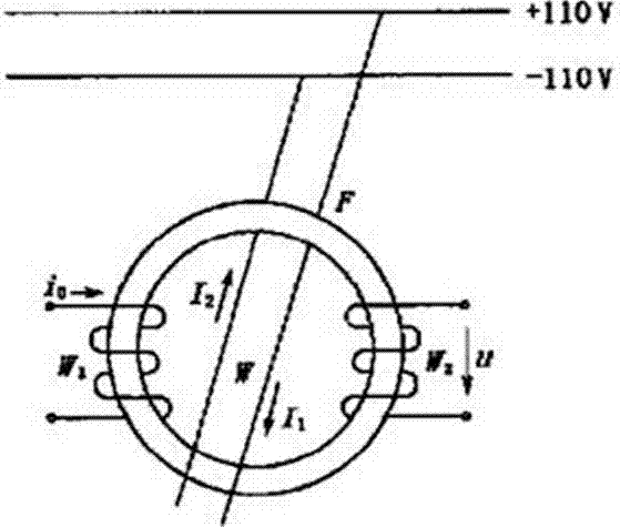
[0013] Such as figure 1 As shown, F is the annular core with high magnetic permeability; I 1 and I 2 are the currents provided by the "positive" and "negative" buses of the DC system to the load respectively; i0 is the excitation current of the triangular wave constant current source; W is the current through the Iron core DC winding; W1 is AC excitation winding; W2 is detection winding.

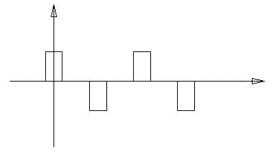
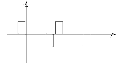
[0014] A method for diagnosing grounding faults in a DC system. The positive and negative busbars of the DC system pass through a ring-shaped iron core with high magnetic permeability, and the two sides of the ring-shaped iron core are respectively equipped with a detection winding and an AC excitation winding that passes through the excitation current of a triangular wave constant current source. Whether the DC system is faulty can be diagnosed by detecting the winding voltage waveform.

[0015] Its method is:

[0016] (1) When the DC system is working normally, I 1 = I 2, at this time th...


PUM


Abstract

The invention discloses a ground fault diagnosis method for a direct current system. The method is characterized in that I1 and I2 are supposed to be respectively current provided to a load by a 'positive' bus and a 'negative' bus of the direct current system, and (1) an induced electromotive force U waveform of a detection winding W2 is positive-negative alternate and is symmetric to a rectangular pulse of a time axis when the I1 is equal to the I2; (2) when the direct current system is faulted and the I1 is higher than the I2, a positive pulse train of induced electromotive force U of the detection winding W2 deviates leftwards while a negative pulse train deviates rightwards; and (3) when the direct current system is faulted and the I1 is lower than the I2, the positive pulse train of the induced electromotive force U of the detection winding W2 deviates rightwards while the negative pulse train deviates leftwards. Complicated change of the direct current system is simplified into change of the induced electromotive force, the method is simple, practical and reliable, a waveform diagram is more visual to observe, and reliable basis and guidance are provided for maintainers to further maintain the direct current system.

Description

technical field [0001] The invention relates to the technical field of power grid safety management, in particular to a method for diagnosing a DC system grounding fault. Background technique [0002] In an ideal state, the capacitance to ground in the DC circuit will not affect the safe operation of DC, so it is often ignored by people. Malfunctioning of protective relays due to excessive capacitance to ground is often not well explained. With the continuous improvement of the grid voltage level, the continuous increase of the capacity of the power station and the expansion of the area of ​​the power station, the distributed capacitance of the wire to the ground and the anti-interference capacitance of the high-frequency switch to the ground are also increasing. Generally, the total capacitance of a 500KV substation to the ground Has reached more than 500uF. The size of the ground capacitance is actually a new problem in the process of integrating loads in a DC syste...

Claims


Application Information

Patent Timeline
Patent Type & Authority Applications(China)
IPC IPC(8): G01R31/02
Inventor 姚楠尚光伟董建刚
Owner NANYANG POWER SUPPLY COMPANY OF STATE GRID HENAN ELECTRIC POWER
Why Eureka
Try Eureka