Microgroove group composite phase change radiator

A technology of composite phase transition and micro-grooves, applied in electric solid devices, semiconductor devices, semiconductor/solid-state device components, etc., can solve the problems of low heat dissipation efficiency, short life of power electronic equipment, uneven heat dissipation, etc. Simple and compact, light weight and low cost effect

Inactive Publication Date: 2013-06-19
HOHAI UNIV CHANGZHOU
View PDF3 Cites 10 Cited by
  • Summary
  • Abstract
  • Description
  • Claims
  • Application Information

AI Technical Summary

Problems solved by technology

[0004] The purpose of the present invention is to overcome the shortcomings of the above-mentioned existing radiators, and provide a micro-groove group composite phase-change radiator that combines heat extraction and heat dissipation, which solves the common problems of uneven heat dissipation and heat dissipation in existing radiators. Problems of low efficiency and short lifetime of power electronics

Method used


Image

  • Microgroove group composite phase change radiator
  • Microgroove group composite phase change radiator
  • Microgroove group composite phase change radiator

Examples


Embodiment Construction

[0037] The present invention will be further described below in conjunction with the accompanying drawings. The following examples are only used to illustrate the technical solution of the present invention more clearly, but not to limit the protection scope of the present invention.

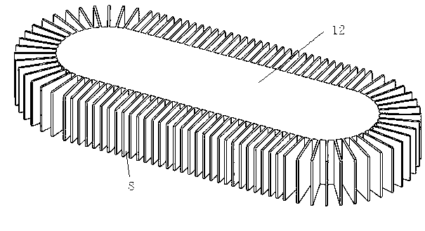
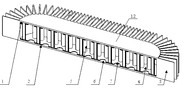
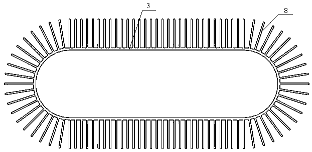
[0038] Such as Figure 1-Figure 8 As shown, the radiator of the present invention includes a radiating surface and a condensing surface oppositely arranged. The radiating surface 1 and the condensing surface 2 are connected by a side wall 3 to form a closed inner cavity 4 . In the inner cavity 4, a plurality of connecting and conveying pipelines 5 are set; on the heat dissipation surface 11 in the inner cavity, a micro-groove group structure composed of a plurality of micro-scale micro-grooves 6 is set for accommodating the heat-taking medium. In the inner cavity 4 , the voids between the delivery lines 5 are filled with porous core material. The end of the delivery pipeline 5 in contact with ...


PUM


Abstract

The invention discloses a microgroove group composite phase change radiator. The radiator comprises a radiating surface and a condensing surface which are opposite to each other, wherein the radiating surface is connected with the condensing surface by a side surrounding plate to form a closed inner cavity, and a plurality of conveying pipelines for connecting the radiating surface with the condensing surface are arranged in the inner cavity; a microgroove group structure consisting of a plurality of microgrooves on micro level is arranged on the radiating surface in the inner cavity and used for accommodating a heat removal medium; a porous core material is filled in gaps between the conveying pipelines in the inner cavity; and a plurality of gaps are formed at one end of each conveying pipeline, which is in contact with the condensing surface, and the liquefied heat removal medium capable of being accommodated on the condensing surface flows out of the conveying pipelines and enters the porous core material. The radiator has heat superconducting capacity, and the heat of a power electronic equipment chip can be timely transferred to the radiating fin part by the microgroove group composite phase change technology; and the radiator is strong in cooling capacity, does not have cooling energy consumption, runs without power, saves energy, and is light in overall weight, small in size, stable in work, high in reliability, low in cost and environment-friendly.

Description

technical field [0001] The invention relates to a heat sink, in particular to a heat sink for power electronic equipment which combines heat taking and heat dissipation. Background technique [0002] Modern power electronic equipment is rapidly developing towards high integration, high density assembly, and high operating speed. As the core chip of power electronic equipment, its operating frequency is getting faster and faster, it consumes more and more power, and emits more and more heat. If the heat dissipation capability of the device is not strong, the power dissipation will cause the temperature of the active area of ​​the chip inside the device to rise and the junction temperature to rise. The failure rate of components is exponentially related to its junction temperature, and the performance decreases with the increase of junction temperature. For every 10°C increase in the operating temperature of the device, the failure rate doubles. [0003] At present, the hea...

Claims


Application Information

Patent Timeline
Patent Type & Authority Applications(China)
IPC IPC(8): H01L23/367H01L23/373
Inventor 张梦妮陈秉岩韩燕高莹张福章周国华刘浩童丽费峻涛朱昌平
Owner HOHAI UNIV CHANGZHOU
Why Eureka
Try Eureka