
Tower-type solar energy heliostat bevel gear passive automatic sun-chasing support

A technology of tower-type solar energy and bevel gears, which is applied in the field of concentrating solar thermal power generation, concentrating photovoltaics, and tower-type concentrating solar heat collection, and can solve the problems of complicated and cumbersome operation and installation of heliostat tracking mechanisms , to achieve the effects of simple installation and operation regulation, improved accuracy, and simplified control procedures and methods

Active Publication Date: 2013-06-19
常州市亚美电气制造有限公司
View PDF5 Cites 17 Cited by
  • Summary
  • Abstract
  • Description
  • Claims
  • Application Information

AI Technical Summary

Problems solved by technology

[0004] With the development of solar technology, the tower solar heat collection and power generation system has become a relatively mature system, but the operation, installation and control of the tracking mechanism of the heliostat are complicated and cumbersome

Method used


Image

  • Tower-type solar energy heliostat bevel gear passive automatic sun-chasing support
  • Tower-type solar energy heliostat bevel gear passive automatic sun-chasing support
  • Tower-type solar energy heliostat bevel gear passive automatic sun-chasing support

Examples


Embodiment 1

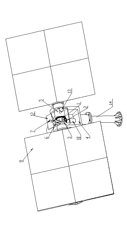
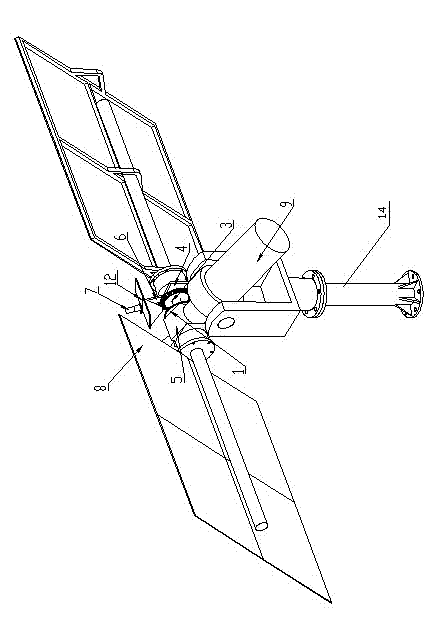
[0035] Embodiment one, such as figure 1 with figure 2 Shown: the pitch rotation reducer 10 is installed on the gear seat 4, and the transition bevel gear 2 of its rotation output shaft is coaxially fixed, and the transition bevel gear 2 will be used as the active driving power source in the pitch direction of the bracket, and the positive drive of the pitch rotation reducer 10 Reversing the rotation will cause the heliostat 8 to pitch.

Embodiment 2

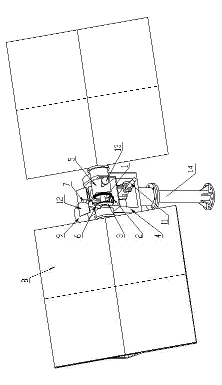
[0036] Embodiment two, such as image 3 with Figure 4 As shown: the fixed end of the linear driver 11 is fixed on the reflection shaft 5, and the moving end of the nut is connected to the gear seat 4. At this time, the linear driver 11 is also used as the active driving power source in the pitch direction of the bracket, through the front and rear of the linear driver 11 nut. The linear motion will drive the heliostat for pitching motion.

[0037] In this way, the photoelectric probe 7 on the incident axis 6 is aimed at the direct sunlight direction through the rotation of the main rotation speed reducer 9 of the support and the pitch motion of the pitch rotation speed reducer 10 or the linear drive 11. According to the movement relationship between the reflective bevel gear 1 and the incident dimension gear 3 and the gear seat 4, the sunlight can shoot to the heliostat along the incident axis 6 and make the reflected light shoot out along the axial direction of the reflecti...


PUM


Abstract

The invention relates to the field of tower-type spotlight solar heat collection technology, spotlight solar energy photo-thermal power generation technology, and spotlight photovoltaic technology, in particular to a tower-type solar energy heliostat bevel gear passive automatic sun-chasing support. A gear base is arranged on the upper portion of the support, heliostats are arranged on both sides of the gear base. A reflection bevel gear, a transitional bevel gear, an incidence bevel gear, a reflection shaft and an incidence shaft are arranged on the upper portion of the gear base. The reflection bevel gear and the incidence bevel gear are co-axial and the reflection bevel gear, the incidence bevel gear and the transitional bevel gear are meshed. Axial directions of two bevel gears are perpendicular to an axial direction of the transitional bevel gear, the reflection bevel gear and the reflection shaft are mutually fixed, and the incidence bevel gear and the incidence shaft are mutually fixed. The silicon or spotlight solar panel is arranged on the incidence shaft, the photoelectric detector is arranged at the tail end of the incidence shaft, one end of the reflection shaft is connected with the main rotation reducer, and the other end of the reflection shaft is connected with a collimation calibration instrument. And a pitching driving structure one or a pitching driving structure two is arranged on the lower portion of the gear base.

Description

technical field [0001] The invention relates to the technical fields of tower-type concentrating solar heat collection, concentrating solar thermal power generation and concentrating photovoltaics, in particular to a tower-type solar heliostat bevel gear passive automatic sun-tracking bracket. Background technique [0002] The concentrated solar thermal power generation system, the concentrated photovoltaic system and the concentrated solar heat collection system do not consume fossil energy and have no pollutant emissions. They are clean energy utilization systems with a harmonious ecological environment. At present, concentrating solar thermal power generation systems such as trough, tower and butterfly systems, concentrating photovoltaic systems and concentrating heat collection systems are also valued by countries all over the world, and the scope of application is gradually expanding. The tower system has initially shown its advantages due to its large scale, small heat...

Claims


Application Information

Patent Timeline
IPC IPC(8): H01L31/042H01L31/052G02B7/198G05D3/00F24J2/54H02S20/32H02S40/22
CPCF24S30/40F24S2030/134Y02E10/47Y02E10/52
Inventor 赵琦杨永健陶明霞
Owner 常州市亚美电气制造有限公司
Learn More