Method and system for positioning fault of optical fiber behind optical splitter in passive optical network (PON)

A passive optical network and optical splitter technology, applied in the optical field, can solve the problems of high personnel participation, huge consumption of manpower, material resources, and large workload, and achieve the effect of low personnel participation, labor saving, and accurate positioning.

Inactive Publication Date: 2013-06-19
CHINA TELECOM CORP LTD
View PDF5 Cites 27 Cited by
  • Summary
  • Abstract
  • Description
  • Claims
  • Application Information

AI Technical Summary

Problems solved by technology

[0007] It is impossible to measure the link quality of multiple optical fibers at one time. If you want to detect the status of which optical fiber, you need to manually use the instrument to measure the test port of the optical cable section. Quickly understand the end-to-end quality status of all links;
[0008] When a fault occurs, because it is impossible to determine the specific fiber core in advance, it is necessary to manually measure and locate the fault core by fiber, which has a large workload, high complexity, and low processing efficiency. However, the PON network has a large scale and a large number of users. Many, this manual, passive optical link monitoring and obstacle handling method is not only extremely inefficient, but also consumes huge manpower and material resources

Method used


Image

  • Method and system for positioning fault of optical fiber behind optical splitter in passive optical network (PON)
  • Method and system for positioning fault of optical fiber behind optical splitter in passive optical network (PON)
  • Method and system for positioning fault of optical fiber behind optical splitter in passive optical network (PON)

Examples


Embodiment Construction

[0029] The following will clearly and completely describe the technical solutions in the embodiments of the present invention with reference to the accompanying drawings in the embodiments of the present invention. Obviously, the described embodiments are only some, not all, embodiments of the present invention. Based on the embodiments of the present invention, all other embodiments obtained by persons of ordinary skill in the art without creative efforts fall within the protection scope of the present invention.

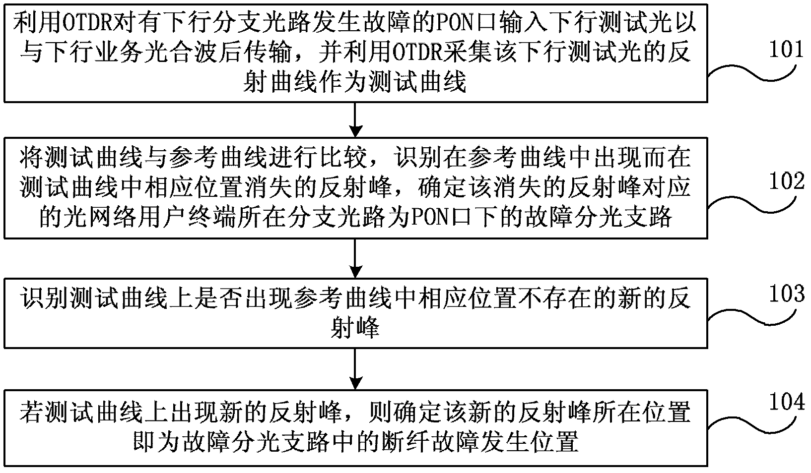
[0030] figure 1 It is a flowchart of an embodiment of a method for locating an optical fiber fault behind an optical splitter in a PON according to the present invention. Such as figure 1 As shown, the method for locating the fault of the optical fiber behind the optical splitter in the PON of this embodiment includes:

[0031]101. When there is a downlink branch optical path failure under the PON port, use an optical time domain reflectometry (Optical Time Domai...


PUM


Abstract

The invention discloses a method and a system for positioning a fault of an optical fiber behind an optical splitter in a passive optical network (PON). The method includes the following steps: when a downward branch optical path below a PON port breaks down, an optical time domain reflector (OTDR) is used for inputting downward test light to the PON port, the downward test light is combined with downward service light and then transmitted, and the OTDR is used for collecting the reflection curve of the downward test light and regarding the reflection curve as a test curve; the reflection curve of the downward branch optical path below the PON port when the downward branch optical path does not break down is regarded as a reference curve, and the test curve is compared with the reference curve so as to identify a reflection peak which exists in the reference curve but disappears at a corresponding position in the test curve and to determine a branch optical path, where an optical network user terminal corresponding to the reflection peak which disappears is located, as a fault light splitting branch below the PON port; whether a novel reflection peak exists in the test curve but does not exist at a corresponding position in the reference curve is identified; and if the novel reflection peak exists, the position of the novel reflection peak is determined as the position, where a broken fiber fault happens, in the fault light splitting branch. The method and the system can be used for quickly and accurately positioning the fault of the optical fiber behind the optical splitter in the PON.

Description

technical field [0001] The invention relates to optical technology, in particular to a method and a system for locating an optical fiber fault behind an optical splitter in a passive optical network. Background technique [0002] The passive optical network (Passive-Optical-Network, hereinafter referred to as: PON) mainly includes: the optical line terminal (Optical Line Terminal, hereinafter referred to as: OLT) at the central office, the optical network unit (Optical Network Unit, hereinafter referred to as: ONU) at the user end ) or an optical network terminal (Optical Network Terminal, hereinafter referred to as ONT), and an optical distribution network (Optical Distribution Network, hereinafter referred to as ODN) for connecting the central office and the user end. Among them, ODN does not contain any electronic devices and electronic power sources, and is entirely composed of passive devices such as optical fibers, optical cables, and optical splitters (Splitter), and ...

Claims


Application Information

Patent Timeline
Patent Type & Authority Applications(China)
IPC IPC(8): H04B10/071H04B10/25
Inventor 尧昱张乐吴艳芹张静赵建军尚逢亮王允
Owner CHINA TELECOM CORP LTD
Why Eureka
Try Eureka