CO2 capture system through pregnant solution self-driven extraction phase splitting and tear regeneration

A self-driven, phase-separation technology, applied in the field of CO2 capture system, can solve problems such as pipeline blockage, and achieve the effect of reducing participation

Inactive Publication Date: 2015-10-07
HUANENG CLEAN ENERGY RES INST
View PDF10 Cites 7 Cited by
  • Summary
  • Abstract
  • Description
  • Claims
  • Application Information

AI Technical Summary

Problems solved by technology

However, this process requires forced cooling or evaporative crystallization, which also increases the amount of public works, and crystallized particles may also cause some engineering problems such as pipeline blockage

Method used


Image

  • CO2 capture system through pregnant solution self-driven extraction phase splitting and tear regeneration

Examples


Embodiment Construction

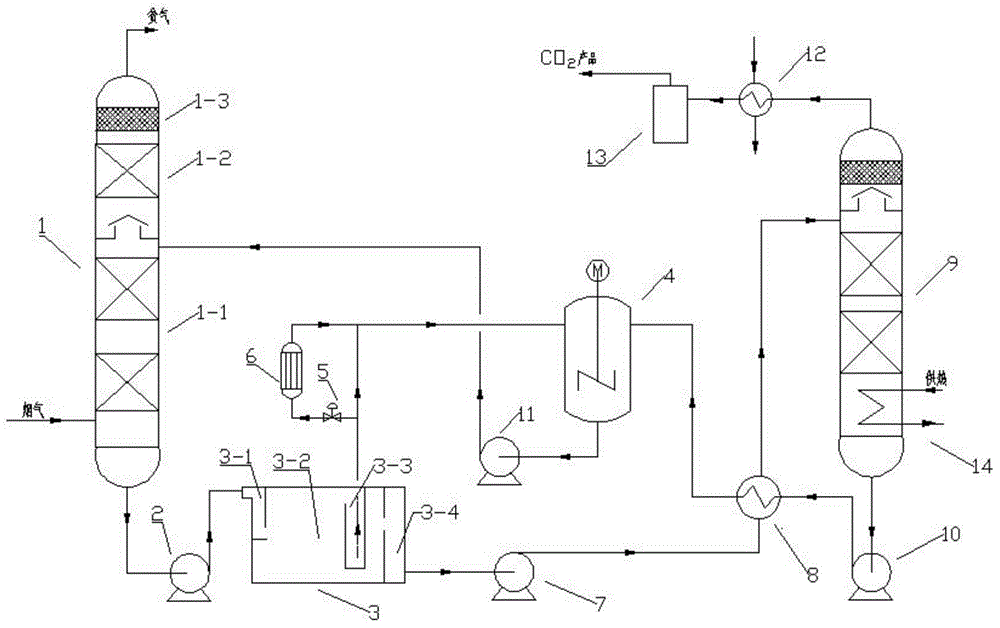
[0012] The present invention will be further described in detail below in conjunction with the accompanying drawings.

[0013] See attached figure, a rich liquid self-driven extraction phase separation and tear regeneration 2 Capture system, including absorption tower 1, absorption tower 1 is composed of absorption section 1-1 at the bottom, washing section 1-2 in the middle and defoaming section 1-3 at the top, the bottom CO of absorption tower 1 2 The rich liquid outlet is connected to the feed liquid inlet of the phase separation clarifier 3 through the rich liquid pump 2; the phase separation clarifier 3 is composed of a feed liquid guide pipe 3-1, a phase separation clarification chamber 3-2, and a light phase collection chamber 3-3 It is composed of the heavy phase collection chamber 3-4; the outlet of the light phase collection chamber 3-3 is divided into two routes, one is directly connected to the inlet of the mixing tank 4, and the other is connected to the inlet of ...


PUM


Abstract

The invention relates to a CO2 capture system through pregnant solution self-driven extraction phase splitting and tear regeneration. A CO2 pregnant solution outlet in the bottom of an absorption tower is connected with the feed liquid guide pipe of a phase splitting clarifier through a pregnant solution pump; the light phase collection chamber outlet of the phase splitting clarifier is divided into two loops, one loop is connected with a mixing tank and the other loop is connected with the mixing tank through a valve and a solution purifier; a heavy phase collection chamber is connected with a regeneration tower through a rich phase pump and a lean-rich heat exchanger; a lean liquid outlet in the bottom of the regeneration tower is connected with the mixing tank through a lean liquid pump and the lean-rich heat exchanger; a solution outlet in the bottom of the mixing tank is connected with absorption liquid of the absorption tower through an absorption liquid pump; a CO2 regenerated gas outlet in the top of the regeneration tower is connected with a gas-liquid separation tank through a cooler; a reboiler is arranged at the bottom of or in the regeneration tower. By layering into liquid-liquid two phases through CO2 pregnant solution self-driven extraction, the concentration and reallocation of components carrying with CO2 in a rich phase are realized, the amount of pregnant solution and the participation degree of water during CO2 regeneration are reduced, and the CO2 regeneration energy consumption and capture cost are reduced to a larger extent.

Description

technical field [0001] The invention belongs to the technical fields of process gas purification, carbon dioxide emission reduction, etc., and specifically relates to a CO 2 capture system. Background technique [0002] carbon dioxide (CO 2 ) is the main greenhouse gas that causes global warming, CO 2 The capture, utilization and storage of sequestration has become one of the hot topics concerned by the international community. my country's coal-fired power generation CO 2 Emissions account for about 50% of total industrial emissions, CO in flue gas from coal-fired power plants 2 The capture and separation of carbon dioxide is an important area of ​​greenhouse gas emission reduction. In addition, there are also large amounts of CO in industrial fields such as steelmaking, cement, and chemical industry (such as ammonia synthesis, hydrogen production, and natural gas purification). 2 capture or separation process. capture or sequester CO 2 The methods mainly include ab...

Claims


Application Information

Patent Timeline
Patent Type & Authority Applications(China)
IPC IPC(8): B01D53/18C01B31/20C01B32/50
CPCY02A50/20Y02P20/151
Inventor 郭东方郜时旺刘练波王昊侯法柱
Owner HUANENG CLEAN ENERGY RES INST
Why Eureka
Try Eureka