Double-lathe-head full-automatic numerically-controlled lathe

A CNC lathe, double head technology, applied in the direction of automatic lathes/semi-automatic lathes, turning equipment, turning equipment, etc., can solve the problems that affect the cutting accuracy of products, complex structure, low work efficiency, etc., and achieve the number of times of manual loading and unloading and turnover The effect of reducing, simplifying the processing process, and improving work efficiency

Inactive Publication Date: 2013-06-26
盛焕君
View PDF6 Cites 9 Cited by
  • Summary
  • Abstract
  • Description
  • Claims
  • Application Information

AI Technical Summary

Problems solved by technology

[0003] The inherent structure and processing method of the above-mentioned lathe often have such defects. For example, to process a stepped shaft, it is first necessary to clamp the workpiece at one end and cut the other end. After the cutting is completed, the workpiece needs to be manually removed and replaced by the workpiece One end is re-clamped, and then the unprocessed end is cut. This processing method is very troublesome, laborious, and low in work efficiency. Especially, the workpiece is easily damaged after two loading and unloading and manual turnover, which also greatly affects the cutting of the product. precision
The published Chinese Patent No. 200820219049.6 "Double Head Column Type Roller Surfacing Machine Tool" also involves a double head machine tool structure, but it is not only complicated in structure and inconvenient to operate, but also mainly used in roller surfacing welding The lathes on the machine tool are different from the above-mentioned lathes in terms of structural composition and working methods

Method used


Image

  • Double-lathe-head full-automatic numerically-controlled lathe

Examples


Embodiment Construction

[0011] The embodiments of the present invention will be described in detail below according to the above-mentioned drawings.

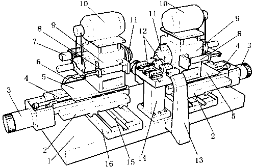
[0012] Such as figure 1 As shown, 1. Body, 2. X-direction moving carriage, 3. Z-direction motor, 4. Z-direction screw, 5. Z-direction moving carriage, 6. X-direction motor, 7. Encoder, 8. Loading and unloading cylinder, 9. Machine head base, 10. Drive motor, 11. Work chuck, 12. Tool holder, 13. Automatic discharge channel, 14. Tool holder, 15. X-direction screw, 16. Guide rail.

[0013] Double-head automatic CNC lathe, such as figure 1 As shown, it belongs to a kind of mechanical equipment for workpiece cutting and processing, and its structure is mainly composed of body 1, machine head, guide rail 16, X-direction moving carriage 2, Z-direction moving carriage 5 and tool holder 14, etc. .

[0014] The fuselage 1 is fixedly placed on the ground, mainly as the installation basis of other parts of the lathe; the guide rail 16 is provided with two, and ...


PUM


Abstract

The invention discloses a double-lathe-head full-automatic numerically-controlled lathe and relates to mechanical equipment used for machining of workpieces. The double-lathe-head full-automatic numerically-controlled lathe is mainly composed of a lathe body, lathe heads, a guide rail, an X-direction moving drag plate, a Z-direction moving drag plate, a knife rest and the like. The lathe heads are of a double-lathe-head structure which allows bidirectional moving and machining at the same time, the knife rest is fixedly arranged between the two lathe heads, a double-face knife rest structure is adopted, and therefore the machining method is that the workpieces can rotate automatically and move along the X-direction and the Z-direction with the lathe heads. The structural change breaks an original structural form and machining method of a traditional lathe, machining process is simple and labor-saving, especially great convenience is brought to parts needing double-head machining, work efficiency is improved greatly, in addition, times of manual assembling and disassembling and turnover are reduced, damage on the workpieces is avoided, and machining accuracy can be effectively guaranteed.

Description

technical field [0001] The invention relates to a full-automatic numerical control lathe used for workpiece cutting, in particular to a double-machine full-automatic numerical control lathe capable of bidirectional and simultaneous moving machining. Background technique [0002] As we all know, lathes are indispensable parts processing equipment in the entire machinery industry. The lathes currently used mainly include semi-automatic or fully automatic ordinary lathes and CNC lathes. The carriage, the Z-direction moving carriage and the tool holder, etc., the head mainly includes the head seat, the workpiece chuck, the drive motor, the encoder and the loading and unloading cylinder, etc., regardless of whether it is an ordinary lathe or a CNC lathe, the head is There is only one, and it is fixed on the fuselage. The guide rail is set on the side of the machine head. The X-direction movable carriage that can move in the X direction and the Z-direction movable carriage that ca...

Claims


Application Information

Patent Timeline
Patent Type & Authority Applications(China)
IPC IPC(8): B23B9/00B23B21/00
Inventor 盛焕君
Owner 盛焕君
Why Eureka
Try Eureka