Brake control apparatus for bar-handle-type vehicle

A joystick and brake control technology, applied in the direction of brake transmission device, hydraulic brake transmission device, bicycle brake, etc., can solve the problems of the influence of the design of the joystick, the trouble of carrying the joystick, etc., and achieve the excellent application versatility Effect

Active Publication Date: 2013-06-26
HITACHI ASTEMO LTD
View PDF5 Cites 4 Cited by
  • Summary
  • Abstract
  • Description
  • Claims
  • Application Information

AI Technical Summary

Problems solved by technology

[0007] Therefore, for a joystick vehicle having an existing mechanical brake, if a joystick vehicle brake control device is used, the master cylinder that operates by operating the brake operating member must be newly mounted on the joystick. In the vicinity of the brake operating member, it is troublesome to mount on the joystick, and the design of the design around the joystick will be affected by the mounting

Method used


Image

  • Brake control apparatus for bar-handle-type vehicle
  • Brake control apparatus for bar-handle-type vehicle
  • Brake control apparatus for bar-handle-type vehicle

Examples


no. 1 approach

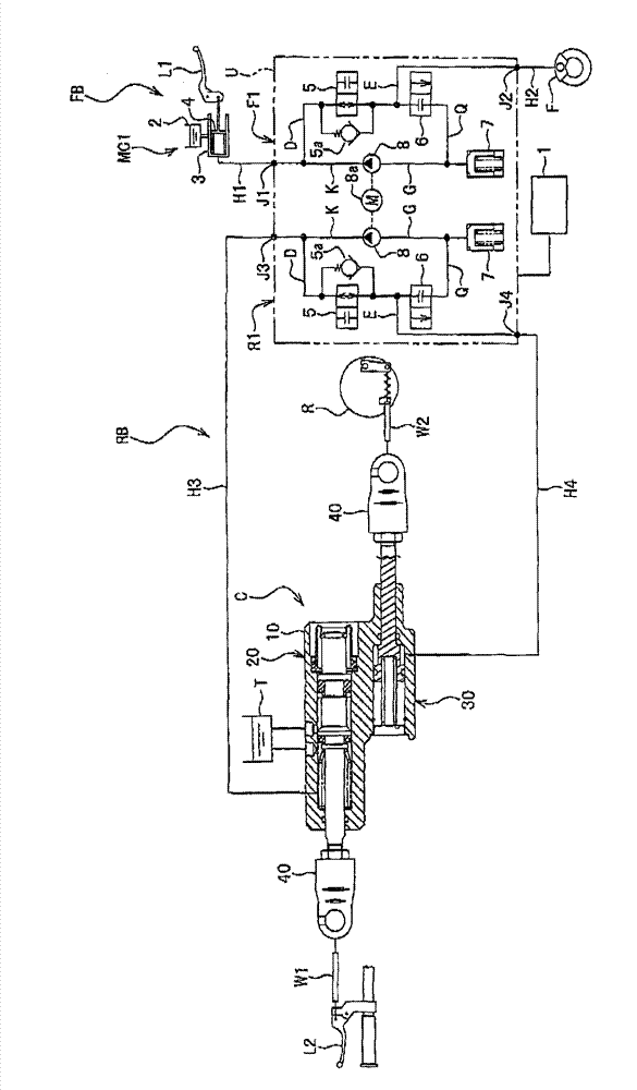
[0047] The brake control device of this embodiment is suitable for vehicles such as motorcycles, tricycles, all-terrain vehicles (ATVs), and four-wheeled vehicles, and it can perform anti-lock braking control and the like on the braking force (braking force) applied to the wheels of the vehicle. hydraulic pressure) is properly controlled. In the following, an example in which the brake control device is applied to a motorcycle is described, but the vehicle on which the brake control device is mounted is not limited.

[0048] like figure 1 As shown, the brake control device of this embodiment is provided with a control unit U that performs brake braking control using hydraulic pressure. The control unit U has a front wheel control system F1 that controls the hydraulic pressure of the brake system FB on the front wheel side, and a rear wheel control system R1 that controls the hydraulic pressure of the brake system RB on the rear wheel side. By properly controlling the braking...

no. 2 approach

[0117] refer to Figure 4 A brake control device according to a second embodiment will be described. In addition, the parts corresponding to the parts described in the first embodiment are denoted by the same symbols, and detailed description thereof will be omitted.

[0118] The present embodiment differs from the above-described first embodiment in that hydraulic pressure is generated by pushing the piston rod 22 of the master cylinder unit 20 through the striker 50 pulled and operated by the wire W. That is, the pulling force generated by the wire W1 is converted into a pushing force via the knocker 50 and drives the piston rod 22 .

[0119] An extension portion 11 is provided at one end of the base body 10 , and a support shaft 12 is provided on the extension portion 11 . The striker 50 is rotatably supported in the vicinity of the opening of the first cylinder bore 21 via the support shaft 12 . The support shaft 12 is arranged at the central portion of the striker 50 i...

no. 3 approach

[0125] refer to Image 6A brake control device according to a third embodiment will be described. Parts corresponding to those described in the first embodiment are denoted by the same symbols, and detailed description thereof will be omitted.

[0126] This embodiment differs from the above-mentioned first embodiment in that the master cylinder unit 20 and the cylinder unit 30 are constructed separately, and there is no change in other points.

[0127] The master cylinder unit 20 is provided on a single body 10A, and the cylinder unit 30 is provided on a separate body 10B from the master cylinder unit 20 .

[0128] According to such a brake control device, since the master cylinder unit 20 and the cylinder unit 30 are respectively provided on the single bases 10A, 10B, these components can be arranged in various positions other than the joystick in the joystick body, Excellent design. It contributes to space saving and miniaturization.

[0129] In addition, the base body 1...


PUM


Abstract

According to the invention there is provided a brake control apparatus for a bar-handle-type vehicle, which does not affect the design around a bar-handle while can be put on the bar-handle-type vehicle. At least one wheel brake forms a mechanical brake driven and operated by a coupling device (C), the coupling device comprises an operating member coupling device and a wheel brake side coupling device, wherein the operating member coupling device is equipped with a first dragging part dragged by a braking operating member, a primary cylinder unit (20) acting by the driving of the first driving part to generate a hydraulic pressure and provide the hydraulic pressure to a control unit, and the wheel brake side coupling device is equipped with a cylinder unit (30) which acts by utilizing the hydraulic pressure outputted by the control unit and a second dragging part linked with the action of the cylinder unit to drag the mechanical brake. The control unit (U), the braking primary cylinder unit (20) and the cylinder unit (30) are arranged in a vehicle body and beyond the bar-handle.

Description

technical field [0001] The present invention relates to a brake control device for a joystick vehicle which can be mounted on a joystick, mainly a joystick-type vehicle such as a motorcycle, a motor tricycle, and an all-terrain vehicle (ATV). Background technique [0002] Conventionally, a brake control device for a joystick vehicle is generally known that controls braking force in a joystick-type vehicle by pressurizing hydraulic pressure with a pump (for example, refer to Patent Documents 1 and 2). [0003] In the technologies described in Patent Documents 1 and 2, the rear wheel brakes are used as mechanical brakes that are traction-operated by a coupling device. action. [0004] Patent Document 1: (Japanese) Patent No. 3608123 [0005] Patent Document 2: (Japanese) Patent No. 3366174 [0006] However, since the joystick brake control device for a vehicle is based on hydraulic pressure control, a master cylinder unit is usually used as a hydraulic pressure source for a...

Claims


Application Information

Patent Timeline
Patent Type & Authority Applications(China)
IPC IPC(8): B62L3/08
CPCB60T8/3225B60T11/046B60T11/102B60T11/16B62L3/023
Inventor 玉井尚利儿玉拓郎
Owner HITACHI ASTEMO LTD
Why Eureka
Try Eureka