All-light-distribution optical system used for light-emitting diode (LED) ball bulb lamp

An LED bulb lamp and optical system technology, applied in the field of optical systems, can solve the problems of increasing the cost of lamps, increasing the complexity of design, etc., and achieve the effect of low cost and good light distribution effect.

Inactive Publication Date: 2013-06-26
建湖光达照明有限公司 +1
View PDF5 Cites 2 Cited by
  • Summary
  • Abstract
  • Description
  • Claims
  • Application Information

AI Technical Summary

Problems solved by technology

However, since the light-emitting angle of LEDs is generally less than 120°, the design of full-angle light-emitting lamps needs to increase the complexity of the design and increase the cost of the lamp

Method used


Image

  • All-light-distribution optical system used for light-emitting diode (LED) ball bulb lamp
  • All-light-distribution optical system used for light-emitting diode (LED) ball bulb lamp
  • All-light-distribution optical system used for light-emitting diode (LED) ball bulb lamp

Examples


Embodiment Construction

[0034] Specific embodiments of the full light distribution optical system for LED bulb lamps of the present invention will be described below in conjunction with the accompanying drawings.

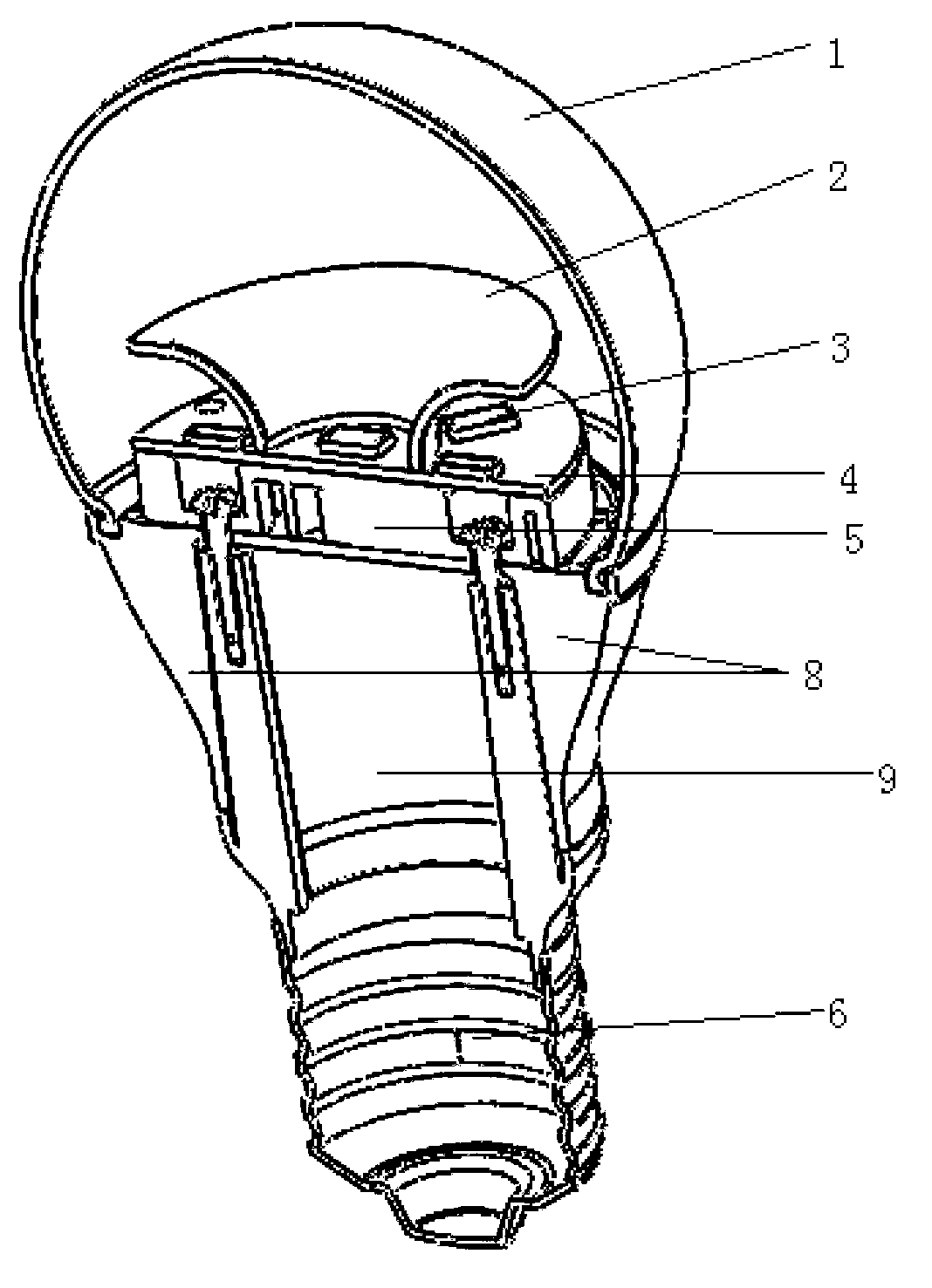
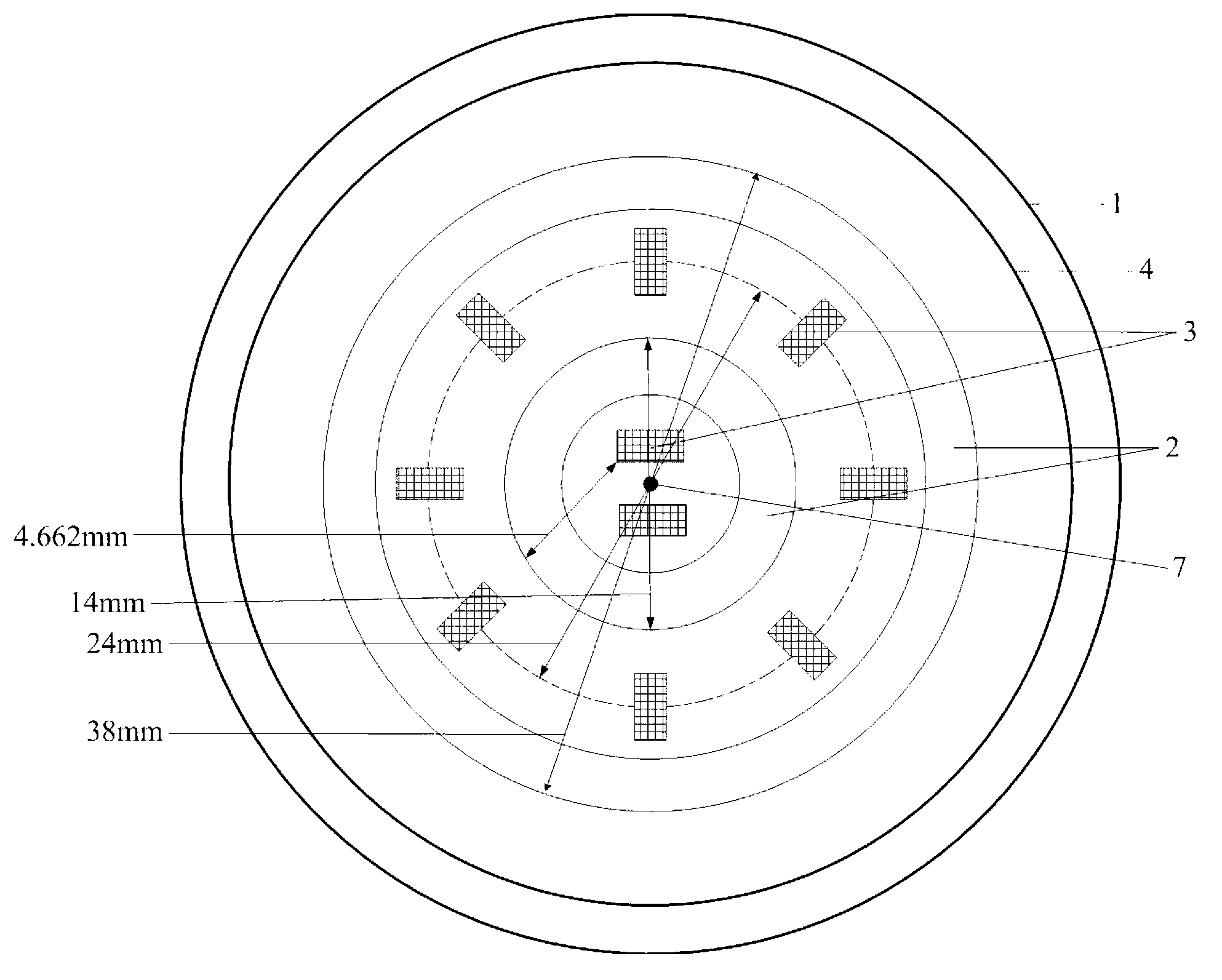
[0035] The full light distribution optical system for LED bulb lamp of the present invention is as figure 1 As shown, it includes a substrate 4 , a plurality of LED chips 3 and a reflector 2 .

[0036] The substrate 4 is located at the bottom of the system and is a cylinder, including: a circuit layer, an insulating layer and an aluminum layer. The aluminum layer is located at the bottom of the substrate 4; the insulating layer is located between the circuit layer and the aluminum layer, and is a polymer filled with high thermal conductivity and high insulation ceramic powder, mainly epoxy resin; the circuit layer is located on the top of the substrate 4 Generally, electrolytic copper foil is used to form a printed circuit through etching to realize the assembly and connection of the devi...


PUM


Abstract

The invention discloses an all-light-distribution optical system used for a light-emitting diode (LED) ball bulb lamp. The all-light-distribution optical system comprises a plurality of LED chips, a light-reflecting cover in a trumpet shape and a substrate. The all-light-distribution optical system is characterized in that the substrate and the light-reflecting cover share the same symmetry axis and the bottom of the light-reflecting cover is connected with the surface of the substrate. The light-reflecting cover is opened from the surface of the substrate and stretches upwards along the symmetry axis to the top portion of the light-reflecting cover in a trumpet-shaped mode. The plurality of LED chips are symmetrically arranged on the surface of the substrate relative to the symmetry axis. A part of the plurality of LED chips are located outside the light-reflecting cover and arranged evenly in an annular shape, the other part of the plurality of LED chips are located inside the light-reflecting cover. Due to the shape and the position of the light-reflecting cover and the arrangement mode of the plurality of LED chips, a part of the light rays emitted by the LED chips shine upwards directly and the other part of the light rays emitted by the LED chips are shot towards other directions through the reflection of the light-reflecting cover, so that light shining angles are increased, the LED ball bulb lamp of the all-light-distribution optical system can achieve the all-light-distribution light distribution effect with ease and cost for achieving the all-light-distribution optical system is also low.

Description

technical field [0001] The invention relates to an optical system applied to LED bulb lamps, in particular to a full light distribution optical system used for LED bulb lamps. Background technique [0002] At present, traditional incandescent bulbs consume a lot of energy and have a short lifespan, and have been gradually replaced by electronic energy-saving lamps. Although electronic energy-saving lamps have improved energy-saving effects, they are not conducive to environmental protection due to the use of many heavy metal elements that pollute the environment. With the rapid development of LED technology, LED bulbs have gradually become a new type of green light source to replace traditional incandescent bulbs and electronic energy-saving lamps. [0003] LED bulbs are generally divided into semi-light distribution type, quasi-light distribution type and full light distribution type according to the light intensity distribution curve. Since the light-emitting angles of se...

Claims


Application Information

Patent Timeline
Patent Type & Authority Applications(China)
IPC IPC(8): F21V3/02F21V7/22F21V23/00F21Y101/02F21Y105/10F21Y115/10
Inventor 郑迪赵昌海李高顺许静珏
Owner 建湖光达照明有限公司
Why Eureka
Try Eureka