Rock tensile-shearing test system

A technology of tensile shear and test system, applied in the field of test system, can solve the problems of tensile shear damage, complex equipment, lack of experimental data, etc., and achieve the effect of perfecting and improving the strength criterion

Active Publication Date: 2013-06-26
INST OF ROCK AND SOIL MECHANICS - CHINESE ACAD OF SCI
View PDF4 Cites 31 Cited by
  • Summary
  • Abstract
  • Description
  • Claims
  • Application Information

AI Technical Summary

Problems solved by technology

For the shear test of rock under tensile conditions, there are seldom reports in domestic and foreign literature, and there are few instruments and equipment that can carry out rock tensile-shear test. Enough attention is paid to it. In addition, the equipment for tensile and shear tests is relatively complicated, including the bonding of rock specimens, the loading method of normal tension, the possible limitation of bonding on lateral deformation, and the influence of eccentricity on rock tensile strength. Compared with the widely used RMT uniaxial compression test, compression-shear test and MTS conventional triaxial test, the rock tension-shear test is much more difficult to operate
In deep-buried and high-stress underground rock engineering, the normal stress of the side wall of the tunnel is 0 due to the excavation and unloading action, and the tangential stress concentration reaches the maximum, and some surrounding rocks will produce normal stress under the vertical shear stress. Tensile stress, when there is a certain space at the bottom of the surrounding rock, the rock mass will undergo tensile s

Method used


Image

  • Rock tensile-shearing test system
  • Rock tensile-shearing test system
  • Rock tensile-shearing test system

Examples


Embodiment Construction

[0015] The present invention will be described in further detail below in conjunction with the accompanying drawings.

[0016] see Attachment

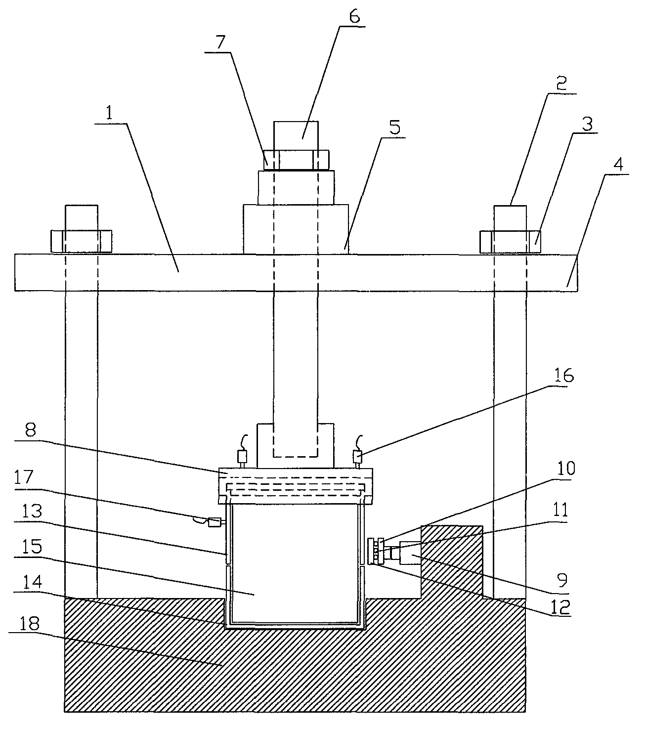
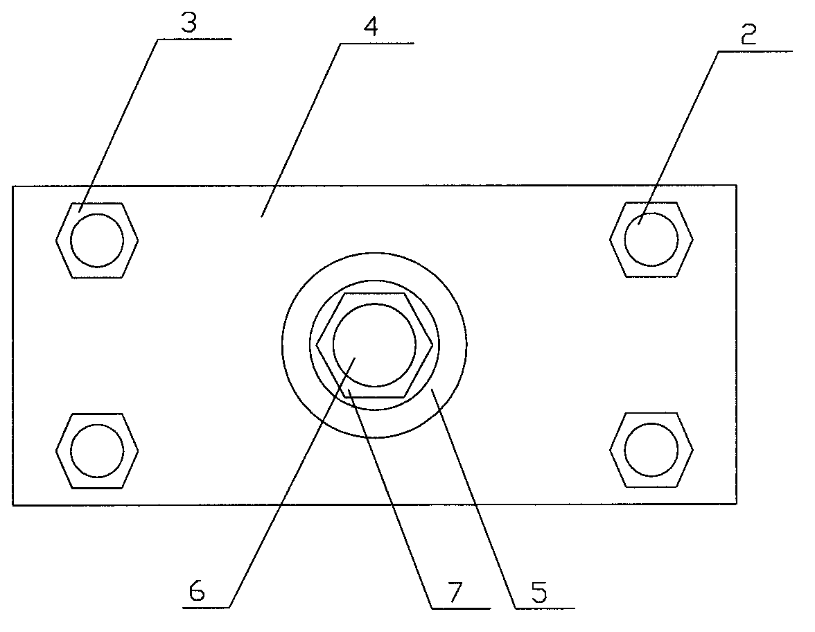
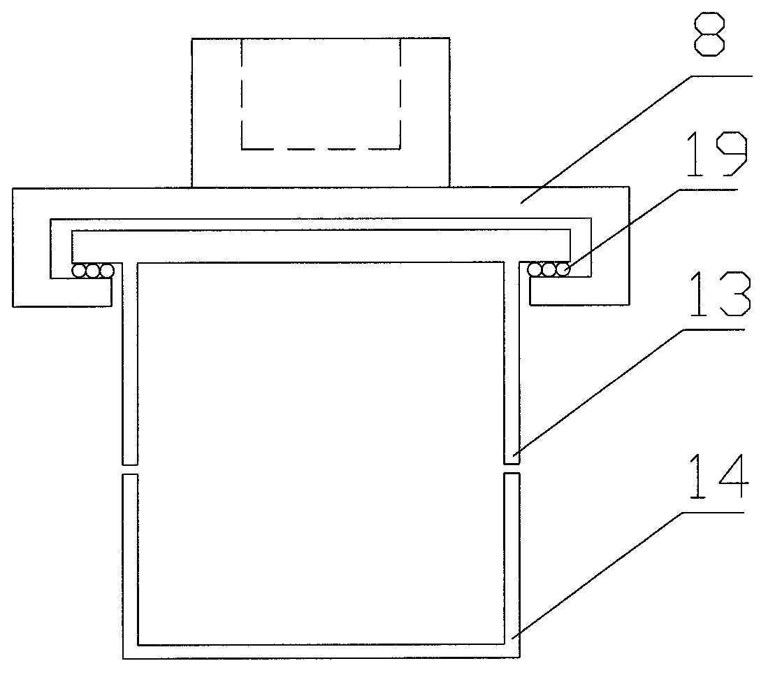
[0017] Rock tensile-shear test system, the test system is composed of a reaction force device 1, a vertical loading system, a horizontal loading system, an upper shear box 13, a lower shear box 14, a measurement system, a hydraulic control system and a base 18. The reaction device 1 described above is composed of four steel beams 2, nuts 3 and bearing plates 4, the bearing plate 4 is fixedly connected to the upper ends of the four steel beams 2 through the nuts 3, and the lower ends of the four steel beams 2 are fixedly connected to each other. in the base 18;

[0018] The vertical loading system is composed of a hollow hydraulic jack 5, a tension column 6, a locking nut 7, and a tension plate 8. The hollow hydraulic jack 5 is located above the bearing plate 4, and the tension column 6 moves through the bearing plate 4. The upper end ...


PUM


Abstract

The invention relates to a tensile-shearing test system for rock experiments in mechanics and belongs to the technical field of geotechnical engineering. The test system comprises a counter-force device, a vertical load system, a horizontal load system, upper and lower shearing boxes, a measurement system and a base, wherein the vertical load system and the upper shearing box are connected through a tensile plate of which the lower end is provided with two guide slots. The direct shear test for the rock under different tensions can be performed; due to the assembled design of the upper and lower shearing boxes, the rock sample can be conveniently adhered and detached; due to the design mode of the tensile plate and the upper shearing box, free deformation of the rock in the horizontal direction under the horizontal thrust can be guaranteed, and the stability of the horizontal load system under the tensile action can be guaranteed according to the roller row which is arranged in the horizontal load direction. The current situation that the strength criterion of the rock can only be researched by employing the compression shear experimental mode at present is changed, the intensity parameters of the rock under the action of different normal tensions can be provided, and the constitutive relation of the rock under the shear-resistant stress is improved and perfected.

Description

technical field [0001] The invention relates to a test system for rock tension-shear test, which belongs to the technical field of geotechnical engineering. Background technique [0002] The shear test of rock under compression is the basic method to obtain the peak shear strength and residual strength of rock under different normal pressures, and it is also the method to obtain the shear strength parameters c, Therefore, it has been widely used in geotechnical engineering, and different compression-shear test equipment has been developed, including large-scale direct shear instrument for indoor test and small portable direct shear for field in-situ test instrument. For the shear test of rock under tensile conditions, there are seldom reports in domestic and foreign literature, and there are few instruments and equipment that can carry out rock tensile-shear test. Enough attention is paid to it. In addition, the equipment for tensile and shear tests is relatively complica...

Claims


Application Information

Patent Timeline
IPC IPC(8): G01N3/10G01N3/24
Inventor 周辉孟凡震张传庆胡善超刘继光渠成堃
Owner INST OF ROCK AND SOIL MECHANICS - CHINESE ACAD OF SCI
Why Eureka
Try Eureka