Method and special device for generating atmospheric pressure DC glow discharge

A DC glow discharge, atmospheric pressure technology, applied in electrical components, plasma and other directions, can solve problems such as small discharge gaps, achieve stable performance, stable operating costs, and wide application prospects.

Inactive Publication Date: 2016-04-20
HEBEI UNIVERSITY
View PDF5 Cites 1 Cited by
  • Summary
  • Abstract
  • Description
  • Claims
  • Application Information

AI Technical Summary

Problems solved by technology

[0004] The second purpose of the present invention is to provide a special device for generating atmospheric pressure DC glow discharge, so as to solve the problem that the discharge gap of the existing atmospheric pressure DC glow discharge device is small

Method used


Image

  • Method and special device for generating atmospheric pressure DC glow discharge

Examples


Embodiment 1

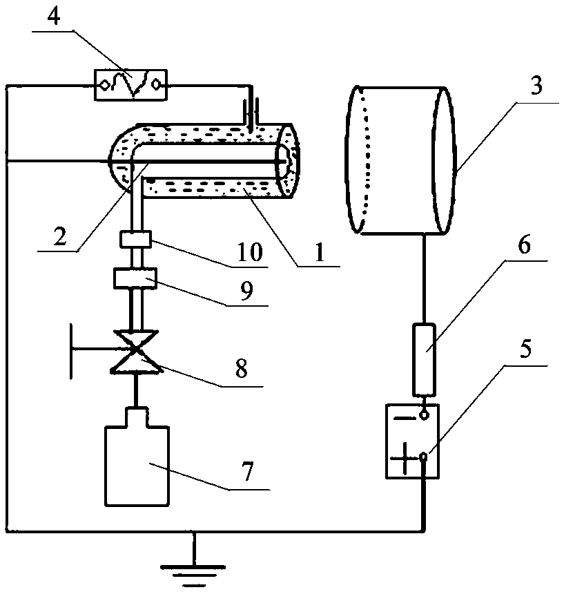
[0025] Such as figure 1 As shown, the DC glow discharge device of the present invention includes a coaxial dielectric tube 1, a metal rod electrode 2, a flat plate electrode 3, a gas supply system and a high voltage power supply. Among them, the dielectric barrier discharge system is composed of the coaxial dielectric tube 1 and the metal rod electrode 2, and the glow discharge system is composed of the flat plate electrode 3 and the metal rod electrode 2.

[0026] Wherein, the coaxial medium pipe 1 is a double-layer tubular airtight container body with an axial central cavity and a U-shaped cross-section. The airtight container body is filled with a conductive liquid (the conductive liquid may be water), and the airtight container body There is an air inlet leading to the central cavity on the side wall, which is used for filling the gas supply system with working gas. The inner diameter of the coaxial medium pipe 1 can be set according to the flow rate of the gas to be intr...

Embodiment 2

[0034] The method for generating atmospheric pressure DC glow discharge in the present invention is as follows: a coaxial dielectric tube 1 with a double-layer tubular airtight container body with an axial center cavity and a U-shaped cross-section is provided, and the airtight container body is filled with conductive liquid. An air inlet leading to the central inner chamber is opened on the side wall of the container body.

[0035] A metal rod electrode 2 is set, and the metal rod electrode 2 is inserted into the central cavity of the coaxial dielectric tube 1 from the sealing end of the coaxial dielectric tube 1, and the rear end of the metal rod electrode 2 is grounded, and the front end is set on the coaxial dielectric tube 1. The open end of the central lumen of tube 1.

[0036] A plate electrode 3 is arranged outside the open end of the coaxial dielectric tube 1 .

[0037] Connect the air supply system to the air inlet.

[0038] Connect one end electrode of the AC high v...

Embodiment 3

[0041] The DC glow discharge device of the present invention can also be completed in another way: one end of the metal rod electrode is grounded, and a plate electrode electrically connected to the DC high-voltage power supply is arranged on the outside of the other end of the metal rod electrode; The upper part is wrapped with an insulating medium such as a ceramic plate, and an aluminum sheet or other conductive medium connected to an AC high-voltage power supply is arranged on the outside of the insulating medium. In this way, an AC high-voltage dielectric barrier discharge system is composed of aluminum sheets, ceramic plates and metal rod electrodes, and a DC high-voltage glow discharge system is formed through the flat plate electrodes and the above-mentioned metal rod electrodes to realize the generation of The active particles and ultraviolet photoionization ignite the DC discharge channel between the metal rod electrode and the plate electrode, thereby producing a con...


PUM


Abstract

The invention relates to an atmospheric direct-current glow discharge method and a special device thereof. The special device structurally comprises a medium stopping discharge system, a glow discharge system, an air supply system and a high-voltage power source. The medium stopping discharge system comprises a coaxial medium tube and a metal rod electrode. The glow discharge system comprises a metal rod electrode and a flat plate electrode, wherein the flat plate electrode is arranged outside an open end of the coaxial medium tube. The high-voltage power source comprises an alternating current high-voltage power source and a direct current high-voltage power source, wherein the alternating current high-voltage power source is electrically connected with conductive liquid in the coaxial medium tube, and the direct current high-voltage power source is electrically connected with the flat plate electrode. The special device is simple in structure, convenient to operate, low in cost and applicable to batch production, and is suitable for industrial line production with no demand for a vacuum device, and widely applicable to fields of material preparation, surface treatment, material etching, ozone synthesis, water treatment, desulfurization and denitrification, sterilization and disinfection and the like.

Description

technical field [0001] The invention relates to a low-temperature plasma discharge method, in particular to a method for generating atmospheric pressure DC glow discharge and a special device thereof. Background technique [0002] DC glow plasma technology has been widely used in the industrial field because of its simple structure, low cost and convenient use. At home and abroad, there have been certain researches and applications on DC glow plasma technology. However, existing technologies and methods have certain defects in the process of generating glow plasma: one is that the existing large-gap DC glow discharge is generally realized under low pressure, which requires the addition of vacuum devices, thereby increasing the The structural complexity of the discharge device is not conducive to the application of plasma technology; second, the current atmospheric pressure glow discharge is only realized in a small air gap on the order of millimeters, which undoubtedly limi...

Claims


Application Information

Patent Timeline
Patent Type & Authority Patents(China)
IPC IPC(8): H05H1/26
Inventor 李雪辰赵欢欢
Owner HEBEI UNIVERSITY
Why Eureka
Try Eureka